SsangYong Rexton. Manual - part 399


  Index      SsangYong     SsangYong Rexton - service repair manual


Search            


Content   ..  397  398  399  400   ..


SsangYong Rexton. Manual - part 399


SSANGYONG  Y200

1F1-4  M162 ENGINE CONTROLS

CLEARING FAILURE CODES

Notice:To prevent Engine Control Module(ECM) damage, the key must be OFF when disconnecting or reconnecting
the power to the ECM (for example battery cable, ECM pigtail connector, ECM fuse, jumper cables, etc.)

Parameters listed in the table may not be exactly the same as your reading due to the type of instrument or other
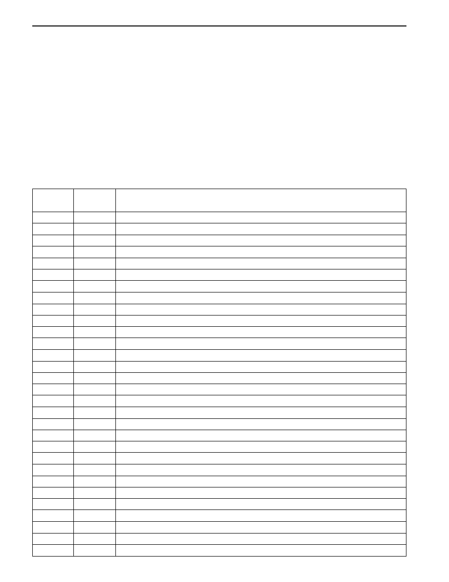
factors. If a failure code is displayed during the “TROUBLE CODE” in scan tool check mode, check the circuit for
the code listed in the table below. For details of each code, turn to the page referred to under the “See Page” for
the re-spective “Failure Code” in the below table.

Failure codes should be cleared after repairs have been completed.

DIAGNOSTIC INFORMATION AND PROCEDURE

FAILURE CODE DIAGNOSIS

FAILURE CODES  TABLE

Failure

Code

00

01

02

03

04

05

06

08

09

10

11

17

18

19

20

21

23

24

25

26

27

29

30

31

32

33

34

35

40

41

Description

Engine coolant temperature sensor low voltage

Engine coolant temperature sensor high voltage

Engine coolant temperature sensor plausibility

Intake air temperature sensor low voltage

Intake air temperature sensor high voltage

Intake air temperature sensor plausibility

Engine coolant temperature insufficient for closed loop fuel control

System voltage too low

Mass air flow sensor plausibility

Mass air flow sensor low voltage

Mass air flow sensor high voltage

Crankshaft position sensor signal failure (no engine revolution signal)

Crankshaft position sensor signal failure (rpm > max. value)

Camshaft position senosr signal : No.1 cylinder recognition failure

Crankshaft position sensor signal failure (gap recognition failure)

Transmission coding failure

CAN communication failure : ASR/MSR

CAN communication failure : ABS

Communication with transponder missing

CAN communication failure : TCU (A/T only)

CAN communication failure : TOD (E32 only)

CAN communication failure : ID 200h not plausible

CAN communication failure : ID 208h not plausible

CAN communication failure : communication initialization failure

Engine rpm output circuit short circuit to battery

Engine rpm output circuit short circuit to ground or open

Fuel pump relay short circuit to battery

Fuel pump relay short circuit to ground or open

Purge control valve short circuit to battery

Purge control valve short circuit to ground or open

See Page

1F1-56

1F1-56

1F1-56

1F1-52

1F1-52

1F1-52

1F1-56

1F1-28

1F1-52

1F1-52

1F1-52

1F1-13

1F1-13

1F1-17

1F1-13

1F1-79

1F1-77

1F1-77

1F1-82

1F1-77

1F1-78

1F1-78

1F1-78

1F1-78

1F1-68

1F1-68

1F1-33

1F1-33

1F1-41

1F1-41

M162 ENGINE CONTROLS  1F1-7

SSANGYONG  Y200

FAILURE CODES TABLE (Cont’d)

Failure

code

167

185

186

187

188

189

190

192

193

194

195

198

199

226

227

228

229

231

232

233

234

235

236

237

238

239

240

241

242

243

244

245

246

247

248

249

250

251

Description

Both setpoint accelerator pedal position sensor defective

Mass air flow sensor and throttle position sensor failure

ECU failure (incompatible CPU)

ECU failure (CPUs communication failure)

ECU failure (CPU 2 configuration failure)

ECU failure (CPU 2 fault)

ECU failure (CPU run time failure between CPUs)

No.5 injector short circuit to battery

No.5 injector short circuit to ground or open

No.6 injector short circuit to battery

No.6 injector short circuit to ground or open

Resonance flap short circuit to battery

Resonance flap short circuit to ground or open

Camshaft actuator short circuit to battery

Camshaft actuator short circuit to ground or open

A/C compressor relay short circuit to battery

A/C compressor relay short circuit to ground or open

ECU failure (CPU 2 cruise control message counter failure)

Over decceleration limit (CPU 2)

Over acceleration limit (CPU 2)

Cruise control lever dual operation (CPU 2)

Cruise control lever safety terminal failure (CPU 2)

Unusual pedal position variation (CPU 2)

Unusual throttle position variation (CPU 2)

Unusual throttle controller monitor data comparison fault (CPU 2)

Unusual accelerator pedal position sensor comparison fault (CPU 2)

Throttle potentiometer comparision fault (CPU 2)

Unusual CPU communication (CPU 2)

Unusual CPU configuration (CPU 2)

A/D converter failure (CPU 2)

Accelerator pedal position sensor setpoint fault between CPU 1 and CPU 2

Position controller setpoint fault between CPU 1 and CPU 2

MSR setpoint fault between CPU 1 and CPU 2

Idle control setpoint fault between CPU 1 and CPU 2

A/D converteroverflow (CPU 2)

ROM f aul t (CPU 2)

RAM f aul t (CPU 2)

Cycle monitor fault (CPU 2)

See Page

1F1-59

1F1-48

1F1-80

1F1-80

1F1-80

1F1-80

1F1-80

1F1-38

1F1-38

1F1-38

1F1-38

1F1-66

1F1-66

1F1-21

1F1-21

1F1-63

1F1-63

1F1-80

1F1-80

1F1-80

1F1-80

1F1-80

1F1-80

1F1-80

1F1-80

1F1-81

1F1-81

1F1-81

1F1-81

1F1-81

1F1-81

1F1-81

1F1-81

1F1-81

1F1-81

1F1-81

1F1-81

1F1-85

SSANGYONG  Y200

1F1-8  M162 ENGINE CONTROLS

This ignition system does not use a conventional
distributor and coil. It uses a crankshaft position
sensor input to the Engine Control Module (ECM). The
ECM then determines Electronic Spark Timing (EST)
and triggers the electronic ignition system ignition coil.

This type of distributorless ignition system uses a
‘‘waste spark” method of spark distribution. Each
cylinder is paired with the cylinder that is opposite it
(1-6 or 2-5 or 3-4). The spark occurs simultaneously in
the cylinder coming upon the compression stroke and
in the cylinder coming up on the exhaust stroke. The
cylinder on the exhaust stroke requires very little of
the available energy tofire the spark plug. The
remaining energy is available to the spark plug in the
cylinder on the compression stroke.

IGNITION SYSTEM

These systems use the EST signal from the ECM to
control the EST. The ECM uses the following
information:

Engine load (mass air flow sensor).

Engine temperature.

Intake air temperature.

Crankshaft position.

Engine speed (rpm).

YAD1F080

SSANGYONG  Y200

1F1-10  M162 ENGINE CONTROLS

IGNITION COIL

YAD1F090

The Electronic Ignition (EI) system ignition coil is located on the cylinder head cover. The double ended coils
receive the signal for the Engine Control Module (ECM) which controls the spark advance.

Each EI system ignition coil provides the high voltage to two spark plugs simultaneously;

T1/1: cylinder 2 and 5

T1/2: cylinder 3 and 4

T1/3: cylinder 1 and 6

The EI system ignition coil is not serviceable and must be replaced as an assembly.

1 Control Cable Connection
2 Ignition Cable
3 Spark Plug Connector
4 Coupling Plug

5a, 5b Secondary Voltage Connection

E Iron Core

L1 Secondary Ignition Coil
L2 Primary Ignition Coil


Content   ..  397  398  399  400   ..