SsangYong Rexton. Manual - part 311
M162 ENGINE MECHANICAL 1B1-47
SSANGYONG Y200
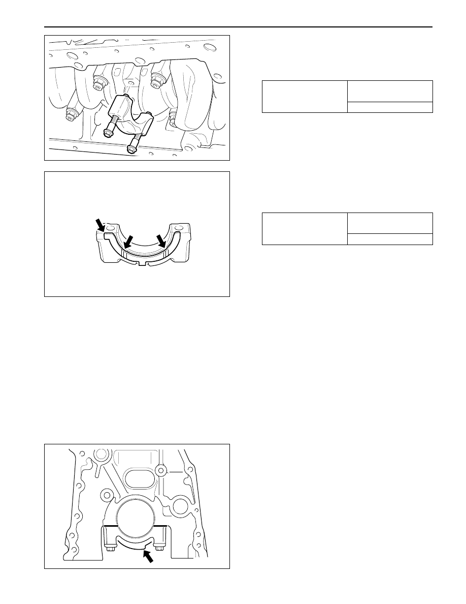
Notice:
•
Make sure the crankshaft bearing cap properly
seated in place in the crankcase side. When
perfectly installed, the projected part (arrow)
locates in the left side (intake manifold side).
•
Assemble so that the projected part of the cap
and crankcase face the same direction.
Removal & Installation Procedure
1. Unscrew the connecting rod bearing cap bolt and
remove the bearing cap.
Installation Notice
2. Unscrew the crankshaft bearing cap bolts and
separate the upper and lower bearing shells and
thrust washers.
Installation Notice
•
Remove the bearing cap from front (pulley side)
to rear.
•
Make sure that the upper and lower bearing
shells do not change each other and coat with
engine oil.
•
The oil grooves (arrows) in the thrust washers
must face outward and insert the thrust bearing
into the bearing cap.
•
There are five kinds of thrust washers by
thickness. Select the proper washer when
repaired.
3. Remove the crankshaft.
4. Installation should follow the removal procedure
in the reverse order.
5. After completion of the installation, check for the
rotating condition of the crankshaft.
•
Make sure that the upper and lower bearing
shells do not change each other.
•
Coat the bearing shell with engine oil.
•
Install the bearing cap according to the
consecutive number.
YAD1B900
YAD1B910
YAD1B920
Tightening Torque
1st step: 40 + 5 N•m
(30 + 3.7 lb-ft)
2nd step: 90° + 10°
Part No. : 601 030 00 62
2.15 mm
Part No. : 601 030 01 62
2.20 mm
Part No. : 601 030 02 62
2.25 mm
Part No. : 601 030 03 62
2.30 mm
Part No. : 601 030 04 62
2.40 mm
Tightening Torque
1st step: 50 - 60 N•m
(37 - 44 lb-ft)
2nd step: 90°