SsangYong Stavic / SsangYong Rodius (2005 year). Manual - part 12
1B-27
CHANGED BY
EFFECTIVE DATE
AFFECTED VIN
ENGINE MECHANICAL
M162 GSL ENG SM - 2005.7
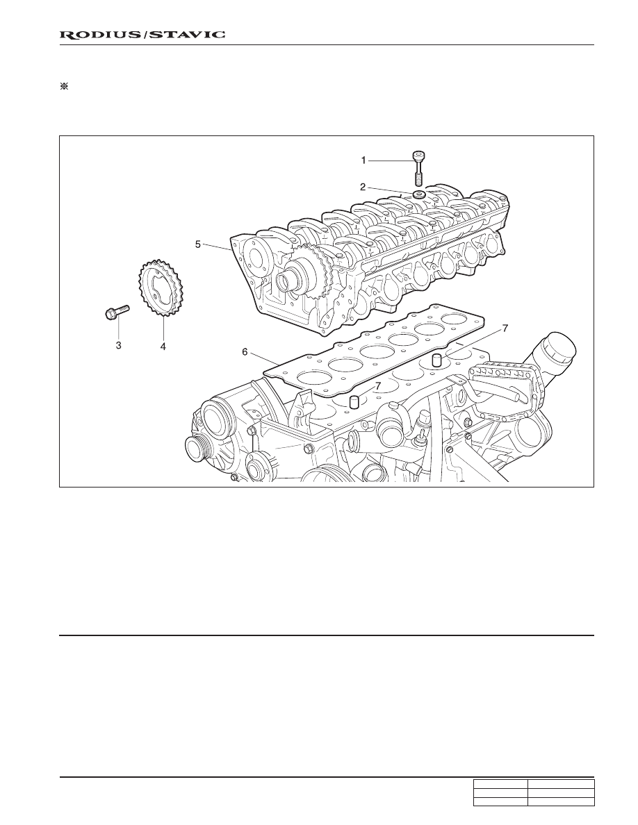
CYLINDER HEAD
Preceding Work: Removal of cylinder head cover
Removal of cylinder head front cover
Removal of upper intake manifold
1. Cylinder head bolt (14 pieces)
......................... 1st step: 55 Nm (141 lb-ft)
2nd step: 90°
3rd step: 90°
2. Washers (14 pieces)
3. Flange bolts (3 pieces)
......................... 1st step: 18 ~ 22 Nm (13 ~ 16 lb-ft)
2nd step: 90° ± 5°
4. Exhaust camshaft sprocket
5. Cylinder head
6. Gasket .......................................................... Replace
7. Dowel sleeve