SsangYong Stavic / SsangYong Rodius (2005 year). Manual - part 11
1B-23
CHANGED BY
EFFECTIVE DATE
AFFECTED VIN
ENGINE MECHANICAL
M162 GSL ENG SM - 2005.7
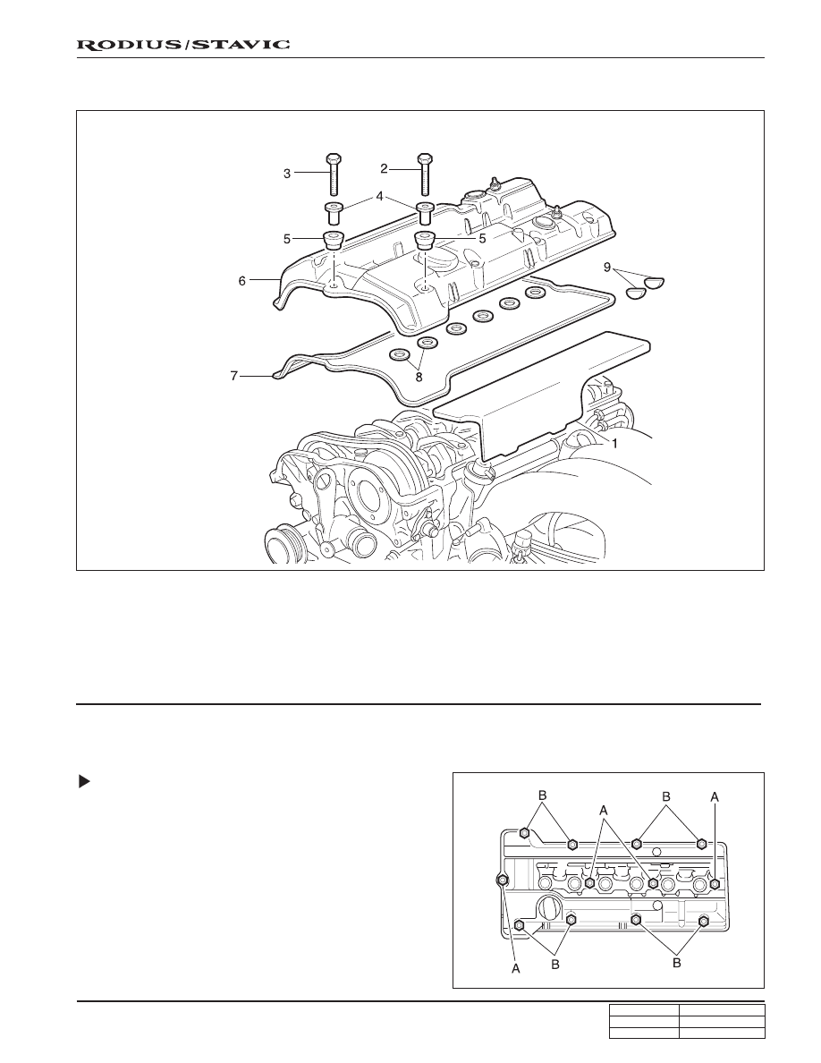
CYLINDER HEAD COVER
1. Ignition cable dust cover
2. Bolt (M6 x 65, 8 pieces) .... 9 ~ 11 Nm (80 ~ 97 lb-in)
3. Bolt (M6 x 50, 4 pieces) .... 9 ~ 11 Nm (80 ~ 97 lb-in)
4. Spacer sleeve
5. Thrust piece
6. Cylinder head cover
7. Gasket .......................................................... Replace
8. Spart plug hole seal ..................................... Replace
9. Camshaft seal .............................................. Replace
Composition of The Cylinder Head
Cover Bolts
A. M6 x 50, 4 Pieces - Bolts + Washers
B. M6 x 65, 8 Pieces - Bolts + Washers