SsangYong Korando III (2010 year). Manual - part 467


  Index      SsangYong     SsangYong Korando III - service repair manual 2010 year


Search            


Content   ..  465  466  467  468   ..


SsangYong Korando III (2010 year). Manual - part 467


04-32

(10) Brake not working alert

The SKM sends the brake not working alert signal for 10 sec. every time the ignition status is changed 

after the 1st cycle (OFF-ACC-IGN-ACC-OFF)

while the brake is not operated.

when the brake pedal is depressed, the system is reset and alert deactivation signal is sent.

when the 10 min. timer is terminated

-

-

(11) Smart key slot detection alert

The SKM sends the smart key slot detection alert signal for 10 sec. when a smart key inserted into 

the slot is detected with IGN OFF and the driver's door open.

-

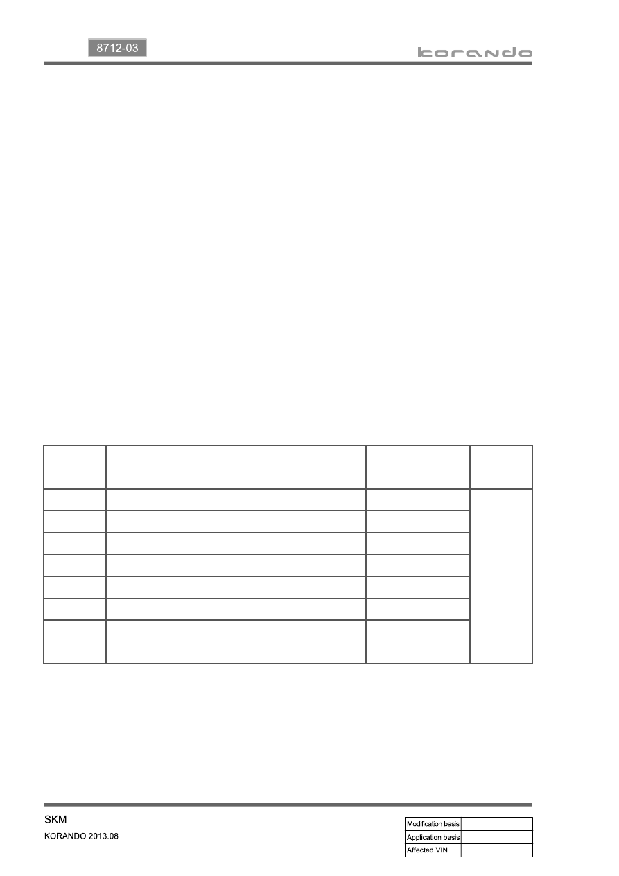
(12) SKM alert priority

1

Smart key out alarm

Outside

1

2

Smart key reminder alarm

Outside

3

Smart key verification failure alarm

Inside

2

4

Transponder verification fail alert

Inside

5

Smart key battery low voltage alert

Inside

6

Transmission position alert

Inside

7

SKM error alert

Inside

8

Brake alert

Inside

9

Clutch alert

Inside

10

Smart key slot reminder alarm

Inside

1

Warning deactivation conditions

Warning transmission conditions

Warning deactivation conditions

when the smart key is removed, the alert deactivation signal is sent.

when the 10 min. timer is terminated

-

-

04-33

8712-03

Start motor

12. SKM IMMOBILIZER SYSTEM

1) System Description

The immobilizer system prevents the vehicle theft by allowing only the authorized key to start the engine. 

The transponder inside the key communicates with the SKM (immobilizer slot) and EMS (ECU) through 

P-CAN communication, and the system permits the engine to start after confirming the encrypted 

coding.

When the START/STOP switch is pressed with the smart key inserted into the immobilizer slot because 

of the smart key battery discharge, the SKM communicates with the EMS (ECU) through P-CAN, and 

the ECU starts to control the engine only the signal is valid. 

A valid key verification time is provided for 10 seconds and the engine can be started during this time. If 

pressing the START/STOP switch again after this 10 seconds, the key verification process is performed 

again.

2) Configuration

Emergency slot

Smart key

SKM

EMS (ECU)

04-34

3) Operating Process

Key verification can be divided into two types, immobilizer key verification and smart key verification. The 

immobilizer verification is applied for the SKM system, and verifies the transponder built in the smart key. 

When the smart key is inserted into the slot, the verification is carried out, overriding the RF signal from 

the smart key.

The power is supplied to the slot when the START/STOP switch is pressed with the smart key inserted 

into the slot, and the smart key transponder verification is carried out by the transponder communication. 

Once the key is verified, a valid key verification time is provided for 10 seconds and the engine can be 

started by pressing the START/STOP switch during this time. If pressing the START/STOP switch after 

this 10 seconds, the key verification process is performed again.

When the ignition is turned ON, the EMS (ECU) sends the challenge message to the SKM through 

the P-CAN. (This is to verify whether the transponder of the smart key is valid. If the verification fails, 

it transmits the re-verification signals 3 times for 2 seconds. If 3rd re-verification fails, the verification 

is deactivated for 10 seconds and re-activated after that.)

The immobilizer slot of the SKM system sends the encrypted cod to the transponder, and the 

transponder re-sends the encrypted code to the immobilizer slot.

The encrypted sent to the immobilizer slot is re-sent to the SKM.

The SKM compares this code with the encrypted code randomly transmitted by the internal logic. 

(System compares the signal from transponder and encrypted signal from the immobilizer control 

unit)

Only when the two signals are identical, it recognizes the key as the verified one and transmits the 

positive message to the ECU. 

The ECU enables the engine to be started.

1. 

2. 

3. 

4. 

5. 

6.

05-3

8010-01

1. SPECIFICATION

Pin No.

Specification

Rated voltage

DC 12.0 V

Operating voltage 

DC 9 V ~ 16 V

CAN operating 

voltage 

DC 7 V ~ 18 V

Inspection voltage

DC 13.5 V

Operating 

temperature 

-30℃ ~ +80℃

Storage temperature 

-40℃ ~ +85℃

Dark current

IGN OFF: 1 mA, 12 V

Measurement condition (at 25℃): 60 seconds after that ignition is 

turned off and stabilized data get

IGN ON: Max. 2 A, 12 V

Measurement condition (at 25℃): during DTC check mode


Content   ..  465  466  467  468   ..