SsangYong Korando III (2010 year). Manual - part 225


  Index      SsangYong     SsangYong Korando III - service repair manual 2010 year


Search            


Content   ..  223  224  225  226   ..


SsangYong Korando III (2010 year). Manual - part 225


03-13

3190-01

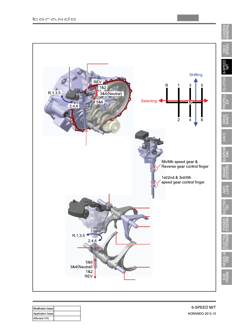
3. SHIFTING MECHANISM

Control shaft

Shift lever

Selector lever

5th/6th speed gear shift lug

Reverse gear shift fork

5th/6th speed gear shift fork

5th/6th speed gear & Reverse 

shift rail

1st/2nd speed gear shift fork 

3rd/4th speed gear shift fork 

1st/2nd, 3rd/4th speed gear shift rail

3rd/4th speed 

gear shift lug 

04-3

0000-00

1. SPECIFICATION

Description

Specification

Operating type

Hydraulic type

Clutch cover

Type

Diaphragm spring strap

Adjusting type

SATIC (Self Adjusting Technology with 
Integrated Cassette) type

Clutch pedal

Type

Suspended type

Max. operating travel

135 ± 3 mm

Pedal free play (Longitudinal)

7.1 ± 3 mm

Pedal free play (Transverse)

3 mm

Clutch disc

Type

Dry type single diaphragm (Rigid type)

Diameter of facing

Outer: 250 ± 1 mm
Inner:160 ± 0.8 mm

Thickness of disc

Free: 8.7 ± 0.3 mm

When loaded: 8.0 ± 0.2 (at 7,800 N)

Numbers of disc

2

Weight

1.18 kg

Flywheel type

DMF (Dual Mass Flywheel)

Setting load of clutch cover assembly

At least 7,800 N

Clutch master cylinder Operating travel

30 mm

Inner diameter

17.46 mm

Concentric slave 
cylinder

Maximum operating travel

12.55 mm

Operating pressure

Maximum 50 bar

Standard

DOT 3 or DOT 4

Capacity

As required

Clutch oil

04-4

2. TIGHTENING TORQUE

Description

Tightening torque

Amount

Clutch housing bolt

Upper (17 mm)

85.0 to 100 Nm

2

Front (14 mm)

54.0 Nm + 20°

1

Rear (14 mm)

51.3 to 56.7 Nm

2

Lower (14 mm)

56.0 to 62.0 Nm

4

Pressure plate assembly bolt (Hexagon 6 mm)

21.0 to 27.0 Nm

6

Concentric slave cylinder bolt (Hexagon 5 mm)

10 to 16 Nm

3

Concentric slave cylinder oil pipe nut

24.5 to 28.4 Nm

Remove the nut if it is 

necessary. (Once 

removed, apply the 

Loctite on the thread 

before installation.)

Master cylinder nut (12 mm)

7.8 to 17.6 Nm

Master cylinder oil pipe nut (10 mm)

14.7 to 17.6 Nm

Master cylinder push rod lock nut

8.8 to 13.7 Nm

Clutch oil chamber screw and bolt (10 mm)

3.9 to 7.8 Nm

Oil pipe nut (10 mm)

14.7 to 17.6 Nm

Clutch pedal mounting nut (12 mm)

7.8 to 17.6 Nm

Stopper bolt

16 to 22 Nm

04-5

0000-00

1. OVERVIEW

The hydraulic clutch transmits the force required to operate the clutch pedal to the concentric slave 

cylinder fitted to the clutch housing as a hydraulic pressure.

(The hydraulic pressure is transmitted in the following order: Clutch pedal - Clutch master cylinder - 

Clutch pipe - Clutch damper - Clutch pipe and hose - Concentric slave cylinder - Pressure plate - 

Flywheel.)

If a driver depress the clutch pedal, the hydraulic pressure is generated in the master cylinder. It is 

transmitted to the concentric slave cylinder through the pipe, resulting in the cylinder being forced out. At 

this time, the clutch disc is forced against the cylinder by pushing the cover. This, in turn, remove the 

flywheel from the pressure plate. As a consequence, the power from the engine will be cut off and the 

gear change can be carried out.


Content   ..  223  224  225  226   ..