SsangYong Korando II (1996-2006 year). Manual - part 410


  Index      SsangYong     SsangYong Korando II - service repair manual 1996-2006 year


Search            


Content   ..  408  409  410  411   ..


SsangYong Korando II (1996-2006 year). Manual - part 410


SSANGYONG  MY2002

8B-56  SUPPLEMENTAL RESTRAINTS SYSTEM

Circuit Description

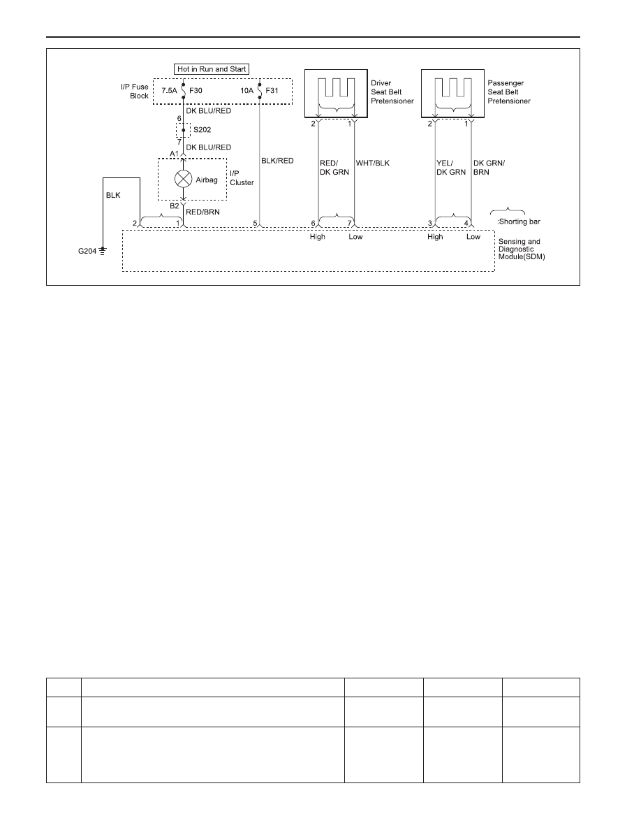
When the ignition switch is first turned ON, ignition voltage
applied to the indicator lamp and also to the sensing
and diagnostic module (SDM) input terminal 5. The SDM
respond by illuminating the airbag indicator in instrument
cluster for 4.5 seconds. If the SDM cannot detect ignition
voltage at terminal 5, a DTC 47 will be set.

DTC 47 Will Set When

DTC 47 will set when during the continuos monitoring,
the SDM fails to detect normal operating voltage at
terminal 5, the input terminal for ignition voltage supply.

DIAGNOSTIC TROUBLE CODE (DTC) 47

BATTERY VOLTAGE IS OUT OF SPECIFICATION

Action Taken

The SDM will illuminates the airbag indicator, but the
indicator will not turn on if the inputs have not been
correctly processed.

DTC 47 Will Clear When

The ignition switch is turned OFF or the problem is
repaired.

KAA8B120

DTC 47 - Battery Voltage is Out of Specification

Caution: The sensing and diagnosis module (SDM)
can maintain sufficient voltage to deploy the airbags
and pretensioners for 0.15 seconds after the ignition
is OFF and the fuse has been removed. If the airbags
or pretensioners are not disconnected, do not begin
s e r v i c e   u n t i l   o n e   m i n u t e   h a s   p a s s e d  a f t e r
disconnecting power to the SDM. Otherwise, injury
could result.

Caution: During service procedure, be very careful
when handling the SDM. Never strike or jar the SDM.
Never power the supplemental restraints system
(SRS) when the SDM is not rigidly attached to the
vehicle. Also SDM mounting nuts must be carefully
tightened to ensure proper operation of the SRS.
The SDM could be activated if it is powered when it
is not rigidly attached to the vehicle, resulting in
unexpected deployment and possible injury.

Perform the SRS Diagnostic System Check.
Is the SRS Diagnostic System Check complete?
1. Repair or replace the faulty wires, terminals or

connectors.

2. Connect all the SRS components.
Is the repair complete?

Step

Action

Value(s)

Yes

No

1

-

 Go to Step 3

 Go to Step 4

3

-

 Go to Step 2

-

SUPPLEMENTAL RESTRAINTS SYSTEM  8B-57

SSANGYONG  MY2002

Measure the voltage at terminal 5 of SDM connector.
Is the voltage within the specified value?
Check fuse F31 in I/P fuse block.
Is the fuse F31 blown?
1. Check for a short circuit and repair it.
2. Replace the fuse.
Is the repair complete?
Measure the voltage at fuse F31.
Is the voltage within the specified value?
Repair power supply to fuse F31.
Is the repair complete?

Repair open circuit between the terminal 5 of SDM
connector and fuse F31.
Is the repair complete?
1. Replace SDM.
2. Connect all SRS components.
Is the repair complete?

Step

Action

Value(s)

Yes

No

4

6

7

8

11 - 14 v

 Go to Step 12

Go to Step 5

5

-

Go to “SRS

Diagnostic

System Check”

-

-

 Go to Step 6

Go to Step 7

-

Go to “SRS

Diagnostic

System Check”

-

9

12

-

Go to “SRS

Diagnostic

System Check”

-

11 - 14 v

 Go to Step 9

Go to Step 8

-

Go to “SRS

Diagnostic

System Check”

-

SSANGYONG  MY2002

8B-58  SUPPLEMENTAL RESTRAINTS SYSTEM

REPAIR INSTRUCTION

ON-VEHICLE SERVICE

SERVICE PRECAUTION

Caution: The sensing and diagnosis module (SDM)
can maintain sufficient voltage to deploy the airbags
and pretensioner for 0.15 seconds after the ignition
is OFF and the airbag fuse has been removed. If the
airbags or pretensioners are not disconnected, do
not begin service until one minute has passed after
disconnecting power to the SDM. If the airbag are
disconnected, service can begin immediately without
waiting for one-minute time period to expire. Failure
to temporarily disable the SRS during service can
result in unexpected deployment, personal injury,
and otherwise unneeded SRS repairs.

DISABLING THE SUPPLEMENTAL
RESTRAINT SYSTEM (SRS)

1. Turn the steering wheel to the straight-ahead

position.

2. Turn the ignition switch to LOCK and remove the key.

3. Remove the airbag fuse F31 in the I/P fuse block

and wait more than one minute for SRS capacitor to
discharge.

ENABLING THE SUPPLEMENTAL
RESTRAINT SYSTEM (SRS)

Enabling the supplemental restraint system (SRS) is
reverse order of “Disabling the Supplemental Restraint
System (SRS)”.

Caution: Staying well away from the inflator
modules, turn the ignition key switch to ON, and
verify that the airbag indicator illuminates for 4.5
seconds and turns OFF. If it does not operate as
described, perform the “SRS Diagnostic System
Check” referring in this section.

HANDLING, INSTALLATION AND
DIAGNOSIS

Airbag modules should not be subjected to
temperature above 65°C (149°F)

An airbag module or sensing and diagnostic module
(SDM) should not be used if it has been dropped
from height of 0.9 meters (3 feet) or greater.

It is very important for the SDM to be installed flat
on the mounting surface, parallel to the vehicle’s
longitudinal axis.

To avoid setting diagnostic trouble codes (DTCs),
do not apply power to the SRS unless all components
are connected or a diagnostic chart request it.

The SRS Diagnostic System Check must be the
starting point of any SRS diagnostics. The SRS
Diagnostic System Check will verify proper airbag
indicator operation and will lead you to correct chart
to diagnose any SRS malfunctions. Bypassing
these procedures may result in extended diagnostic
time and incorrect parts replacements.

REPAIRS AND INSPECTIONS
REQUIRED AFTER AN ACCIDENT

Caution: any repairs to the vehicle’s structure must
return it to the original production configuration.
Deployment requires replacement of SDM, the
inflator modules, and a dimensional inspection of
the steering column.

If any SRS components are damaged, they must
be replaced. If SRS components mounting points
are damaged, they must be repaired or replaced.

Never use SRS parts from another vehicle. This does
not include remanufactured parts purchased from
an authorized source.

Do not attempt to service the SDM, the clock spring,
or other airbag modules, these items must be
replaced if they are defective.

Verify the part number of replacement airbag
modules. Some inflator modules look identical but
contain different internal components.

ACCIDENT WITH DEPLOYMENT -
COMPONENTS REPLACEMENT

All SRS components must be replaced after frontal crash
involving airbag deployment. After deployment, a
powdery residue may be on the surface of the airbag.
The powder consists primarily of cornstarch (used to
lubricate the bag as it inflates) and by-products of the
chemical reaction. Sodium hydroxide dust (similar to
lye soap) is produced as a by-product of the deployment
reaction. The sodium hydroxide then quickly reacts with
atmospheric moisture and is converted to sodium
carbonate and sodium bicarbonate (also known as
baking soda). Therefore, it is unlikely that sodium
hydroxide will be present after deployment. Replace
the following SRS components.

Caution: Wear gloves and safety glasses during the
disposal procedure. Refer to “Deployed Airbag
Module Disposal Procedure” in this section.

The SDM.

Airbag modules and pretensioners

SRS wiring

Clock spring

SUPPLEMENTAL RESTRAINTS SYSTEM  8B-59

SSANGYONG  MY2002

KAA8B130

ACCIDENT WITHOUT DEPLOYMENT
- COMPONENT INSPECTION

Certain inspection must be performed after any crash,
whether the airbag has deployed or not:

The steering column must be dimensionally
inspected.

Inspect the knee bolsters and mounting points for
distortion, bending, cracking, or other damage.

Inspect the instrument panel (I/P) and steering
column reinforcement plate for distortion, bending,
cracking, or other damage.

Inspect the I/P braces for distortion, bending,
cracking, or other damage.

Inspect seat belt and mounting points. Refer to
Section 8A, Seat Belts.

SENSING AND DIAGNOSTIC
MODULE (SDM)

Caution: during service procedures, be very careful
when handling the SDM. Never strike or jar the SDM.
Never power up the SRS when the SDM is not rigidly
attached to the vehicle. All SDM mounting nuts must
carefully tightened, to ensure proper operation of
the SRS. The SDM could be activated if it is powered
while not rigidly attached to the vehicle, resulting
in unexpected deployment and possible injury.

Important: If the vehicle interior has been exposed to
extensive water intrusion such as water leaks, driving
through high water, flooding, or other causes, the sensing
and diagnostic module (SDM) and SDM connector may
need to be replaced. With the ignition OFF, inspect the
area around the SDM, including the carpet. If any
significant soaking or evidence of previous soaking is
detected, the water must be removed, the water damage
repaired, and the SDM and SDM connector must be
replaced. Before attempting any of these repairs, the
supplemental restraint system (SRS) must be disabled.
Refer to”Disabling the Supplemental Restraint System
(SRS)” in this section.

Removal and installation Procedure

1. Disable the supplemental restraint system (SRS).

Refer to “Disabling the SRS” in this section.

2. Remove the connector position assurance lock,

which is tethered to the SDM connector.

3. Disconnect the SDM electrical connector.
4. Remove the SDM mounting nuts and grounding nut.

Installation Notice

5. Remove the SDM.
6. Installation should follow the removal procedure

in the reverse order.
Notice: Enable the SRS. Refer to “Enabling the SRS”
in this section.

Tightening Torque

12 N•m (106 lb-in)


Content   ..  408  409  410  411   ..