SsangYong Korando II (1996-2006 year). Manual - part 409
SSANGYONG MY2002
8B-52 SUPPLEMENTAL RESTRAINTS SYSTEM
Circuit Description
When the ignition switch is turned to ON, the sensing
and diagnostic module (SDM) will perform tests to
diagnose critical malfunctions within SDM itself. Upon
passing these tests ignition and deployment loop
voltages are measured to ensure that they are within
their respective normal voltage ranges. The SDM then
proceeds with resistance measurement test. Passenger
seat belt pretensioner low terminal 4 is grounded
through a current sink. The current source is connected
to passenger seat belt pretensioner high terminal 3 to
allow a known amount of the current flow. By monitoring
the voltage difference between passenger seat belt
pretensioner high and passenger seat belt pretensioner
low, the SDM calculates the combined resistance of
the passenger seat belt pretensioner inflator module,
the harness wiring, and connector terminal contacts.
DTC 24 Will Set When
DTC 24 will set when the resistance of passenger seat
belt pretensioner deployment loop is below a specified
DIAGNOSTIC TROUBLE CODE (DTC) 24
PASSENGER SEAT BELT PRETENSIONER DEPLOYMENT LOOP
RESISTANCE LOW
value (1.4 ± 0.5
Ω
). The test is run once each ignition
cycle during the resistance measurement test when
the ignition voltage is above a specified value.
Action Taken
The SDM will turn on the airbag indicator (blink mode
4) and set DTC 24. And passenger seat belt
pretensioner deployment loop shutdown.
DTC24 Will Clear When
The ignition switch is turned OFF or the scan tool
CLEAR CODES command is received.
Diagnostic Aids
All intermittent condition is likely to be the caused by
a poor connection from the passenger seat belt
pretensioner to the SDM terminal 3 or 4. The test for
this DTC is run only while the airbag indicator is
performing the start-up test. When a scan tool CLEAR
CODES command is issued and the malfunction is
still present, the DTC will not reappear until next ignition
cycle.
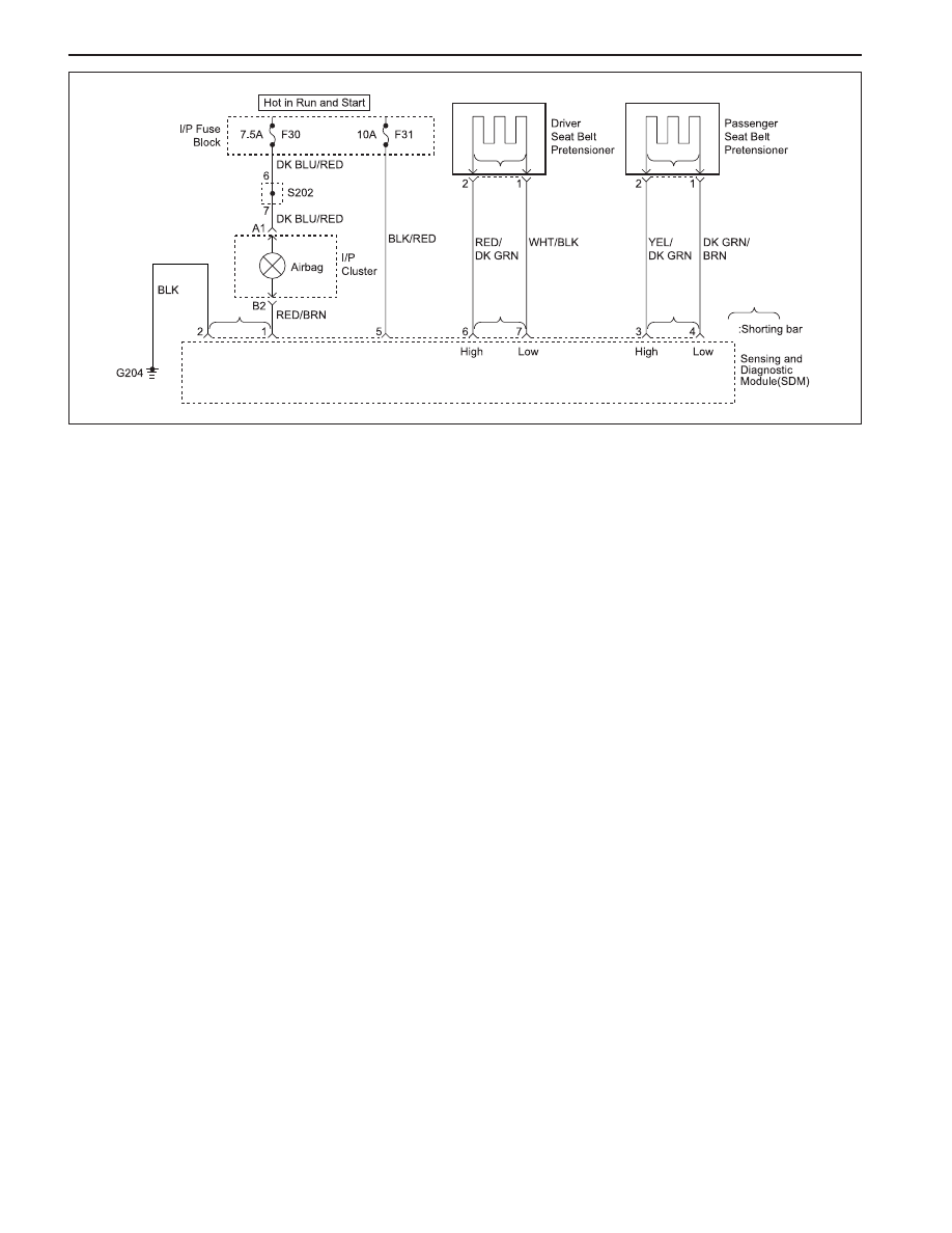
KAA8B120
DTC 24 - Passenger Seat Belt Pretensioner Deployment Loop Resistance Low
Caution: The sensing and diagnosis module (SDM)
can maintain sufficient voltage to deploy the airbags
and pretensioners for 0.15 seconds after the ignition
is OFF and the fuse has been removed. If the airbags
or pretensioners are not disconnected, do not begin
s e r v i c e u n t i l o n e m i n u t e h a s p a s s e d a f t e r
disconnecting power to the SDM. Otherwise, injury
could result.
Caution: During service procedure, be very careful
when handling the SDM. Never strike or jar the SDM.
Never power the supplemental restraints system
(SRS) when the SDM is not rigidly attached to the
vehicle. Also SDM mounting nuts must be carefully
tightened to ensure proper operation of the SRS.
The SDM could be activated if it is powered when it
is not rigidly attached to the vehicle, resulting in
unexpected deployment and possible injury.