SsangYong Korando II (1996-2006 year). Manual - part 41
1E1 -- 10 M162 ENGINE ELECTRICAL
DAEWOO MY_2000
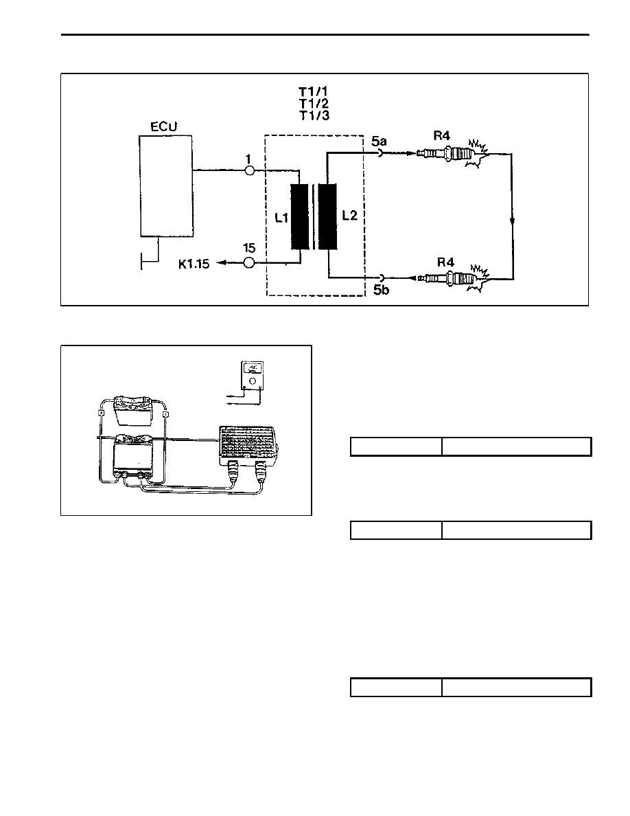
Circuit Diagram
Inspection & Maintenance Procedure (for
MSE)
1. While the ignition switch is in ’OFF’ position, remove
the wiring connectors (1 and 15) from ignition coil and
measure the primary resistance between terminal
No.1 and No.15.
Specified Value
0.9 -- 1.6 Ω (20 °C)
Notice: If out of specified value, replace the ignition coil.
2. During engine cranking, measure primary voltage
(T1/1) between ECU terminal No. 71 and No. 69.
Specified Value
200 -- 350 V
Notice
D
Measure remaining cables.
-- T1/2 : No. 72 and 69.
-- T1/3 : No. 70 and 69.
D
If out of specified value, check ignition cable and
ECU.
3. Using a multi--tester, measure the secondary coil re-
sistance between 5a and 5b.
Specified Value
6 -- 8.5 kΩ