Skoda Kodiaq (2019 year). Manual - part 16


  Index      Skoda     Skoda Kodiaq (2019 year) - manual in english


Search            copyright infringement  


Content      ..     14      15      16      17     ..


Skoda Kodiaq (2019 year). Manual - part 16


Mode selection and Infotainment display

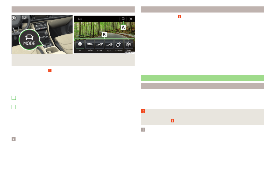
Fig. 308  Button for selecting the driving mode / Display in Infotainment

screen

Read and observe   on page 251 first.

Display of the driving mode menu

Press the  

» Fig. 308

 button.

The following function surfaces are displayed on the Infotainment screen

» Fig. 308

.

Information on setting the currently selected mode

Setting the Individual mode
Driving mode menu

The driving mode selection is performed in one of the following ways.

By repeatedly pressing the button .

By tapping the relevant function surface on the Infotainment screen

» Fig. 308

,

After switching the ignition off and on, the Normal mode is set.

Note

The currently selected driving mode is displayed in the infotainment system

in the status bar next to the symbol .

The setting for the individual mode is stored in the active personalisation user

account 

» page 59

.

A

B

Settings for individualmode

Read and observe   on page 251 first.

In the Individual mode, the following menu items can be set.

DCC: - Sets the shock characteristics

Steering: - Set the power steering characteristics

Drive: - Sets the drive characteristics

ACC: - sets the vehicle acceleration when adaptive cruise control is activated

Dynamic Cornering light: - Sets the Full LED headlight characteristics

Air conditioning: - Sets the Climatronic characteristics

Engine sound: - Sets the engine noise in the vehicle

Reset mode - Setting for all menu items in Individual mode to Normal

Cancel - Keep the current settings

Reset - cancels all menu items in the Normal mode

Proactive occupant protection (Crew Protect Assist)

Introduction

ProActive passenger protection (following known as system) increases pas-

senger protection in the front seats in situations that could lead to vehicle im-

pact or overturning.

WARNING

Please take note of the general points relating to the use of assistance sys-

tems 

» page 216,

   in section Introduction.

Note

The system component service life is monitored electronically. Further infor-

mation 

» page 44

 Safety systems.

253

Assist systems

-------------------------------------------------------------------------------------------------------------------------------------------------------------

Function

Read and observe   on page 253 first.

In critical driving situations (e.g. during emergency braking or a sudden change

in direction), the following steps can be taken separately or combined in order

to reduce the risk of serious injury.

The front passenger's and driver's seatbelts, if worn, are automatically ten-

sioned closely over the body.

Opened electrically powered door windows are closed automatically up to a

gap of about 5 cm from the edge.

The sliding/tilting roof is closed.

Once the critical driving situation has passed, the tension on the seatbelts will

be released again.
The system operates at two levels of protection.

The first level of protection

The system already intervenes in situations that may occur during dynamic

driving. As a result, this primarily helps to keep the driver and the passenger in

the correct seated position.
The first protection level can be deactivated in one of the following ways.

In the infotainment system, in menu 



/  tap on function surface  → Driv-

er assistance.

Deactivating the TCS

» page 218

.

By selecting the driving mode Sport 

» page 253

.

By selecting the driving mode Offroad 

» page 219

.

After switching the ignition off and on, the system is activated in both levels of

protection.

The second level of protection

The system intervenes only if the situation is evaluated as critical, such as

when panic braking at high speeds.
This level of protection cannot be deactivated.

Vehicles with the Front Assist system

Using this information, a system intervention may also occur when there is the

danger of a collision with an obstacle detected in front of the vehicle.

Lane Departure Warning (Lane Assist)

Introduction

Fig. 309 

Sensor for Lane Assist

The lane departure warning (following known as system) helps to keep the ve-

hicle between the boundary lines of a lane.
The system recognises the boundary lines of the lane using a sensor 

» Fig. 309

.

When the vehicle approaches a detected line between lanes, the system

makes a light movement of the steering wheel in the opposite direction to the

boundary line. This corrective steering intervention can be manually overridden

at any time.

WARNING

Please take note of the general points relating to the use of assistance

systems 

» page 216,

   in section Introduction.

Lane Assist can help you keep the vehicle within the lane. However, it

does not steer the vehicle for you. The driver retains full responsibility for

steering at all times.

Some objects or markings on the road can be recognised as the boundary

lines - an erroneous steering intervention may be the result.

WARNING

The system may not be able to recognise the boundary line, or recognise it

incorrectly, for example, in the following situations.

When visibility is poor, (e.g. fog, heavy rain, thick snowfall).

When driving in “sharp” bends.

The sensor is blinded by the sun or oncoming traffic.

The field of view of the sensor is limited by an obstacle or a preceding ve-

hicle.

254

Driving

-------------------------------------------------------------------------------------------------------------------------------------------------------------

CAUTION

Do not attach any stickers or similar objects in front of the sensor on the wind-

screen to avoid impairing the functions of the system.

Note

The system is designed for driving on motorways and roads with adequate

longitudinal markings.

The system can detect both continuous and broken lines.

Settings in Infotainment

Read and observe   and   on page 254 first.

In the infotainment system, in menu 



/  tap on function surface  → Driv-

er assistance.

Lane Assist (lane departure warning system) - Settings for Lane Assist

Active - Activate/deactivate the assistant

Adaptive lane guidance - Activate/deactivate adaptive lane guidance

Operation

Fig. 310  Monochromatic display of the instrument cluster: Examples of

system indications

Fig. 311  Colour display of the instrument cluster: Examples of system

indications

Read and observe   and   on page 254 first.

System displays

» Fig. 310

 and 

» Fig. 311

The system is active, but not ready to intervene.
The system is active and ready to intervene.
The system intervenes when approaching the right-hand boundary lane.
Adaptive tracking takes place.

The system can intervene when the following basic conditions are present.

The system is activated.
The vehicle speed is higher than about 65 km/h (not applicable to vehicles

with the traffic jam assistant 

» page 256

).

The boundary line of at least one side of the lane is detected.
The driver's hands are on the steering wheel.
The lane is more than 2.5 m in width.

If the turn signal is switched on (e.g. when turning), no steering intervention

takes place when the vehicle approaches the boundary line. The system re-

gards the situation as an intended lane change.

Warning lights in the instrument cluster

The system is active, but not ready to intervene.
The system is active and ready to intervene or is currently intervening.

Adaptive lane assist

Adaptive tracking helps to keep the vehicle in the position between the boun-

dary lines selected by the driver, by means of steering intervention.

255

Assist systems

-------------------------------------------------------------------------------------------------------------------------------------------------------------

If the position within the lane is changed, the system quickly adapts and holds

the newly-selected position.

Steering wheel vibrations

In the following situations, it may occasionally be the case that due to the

steering wheel vibrations the syst4em indicates that a driver steering interven-

tion is required.

The system is not able to keep the vehicle by a within the lane due to a steer-

ing intervention.

During an intense system-related steering intervention, the system suddenly

cannot recognize the boundary lines.

WARNING

The system function may be restricted if, for example there is danger due

to ruts on a downhill road or in a crosswind.

Activation / deactivation

Read and observe   and   on page 254 first.

The activation/deactivation of the system can be carried out in one of two

ways.

In the instrument cluster display 

» page 57

Assist systems menu item.

In Infotainment 

» page 255

Settings in Infotainment.

Adaptive tracking can also be enabled or disabled In Infotainment.
After switching off and switching on the ignition, the system setting is re-

tained.

Note

The system setting is stored (depending on the Infotainment type) in the ac-

tive user account personalisation 

» page 59

.

Malfunctions

Read and observe   and   on page 254 first.

If the system is not available, an appropriate message appears in the display of

the instrument cluster.

Sensor covered / dirty

If the windscreen is dirty, iced or misted up in the sensor area, a message ap-

pears indicating that there is no sensor view. Clean the windscreen or remove

the obstacles from the sensor area.

System unavailable

If the system is unavailable, a message concerning the unavailability appears.

Try to re-activate the machine. If the system still is not available, seek the as-

sistance of a specialist garage.

System fault

In the case of a system fault, an error message appears. Seek help from a spe-

cialist garage.

Request to take over steering

If the system detects that there are no hands are on the steering wheel, this

will not work properly. You will be prompted to take over steering. Place your

hands on the steering wheel.

Traffic jam assistant

Introduction

WARNING

Please take note of the general points relating to the use of assistance

systems 

» page 216,

   in section Introduction.

The driver must always have hands on the steering wheel and be ready to

take over steering of the vehicle himself (accelerate or brake).

Note

The system is designed primarily for use on motorways.

Function

Read and observe   on page 256 first.

The traffic jam assistant (referred to as system) helps to keep the vehicle with-

in the lane at speeds below 65 km/h while keeping the distance to the vehicle

ahead.
Only vehicles with automatic transmission, Lane Assist and ACC can be equip-

ped with the system.

256

Driving

-------------------------------------------------------------------------------------------------------------------------------------------------------------

The traffic jam assistant works using the functions of the Lane Assist systems

» page 254

 and ACC 

» page 244

. For this reason, the chapters relating to these

systems must be read carefully and the safety instructions listed therein must

be observed.

Operating conditions

Read and observe   on page 256 first.

The system activation occurs automatically whilst fulfilling the following

basic conditions.

Lane Assist with the adaptive tracking is enabled, the boundary lines on

both sides are recognized lane 

» page 254

.

ACC is activated and the regulation 

» page 244

 follows.

The vehicle speed is below 65 km/h.

Assistant for emergencies

Introduction

WARNING

Please take note of the general points relating to the use of assistance

systems 

» page 216,

   in section Introduction.

The system is intended for emergency situations when the driver is sud-

denly unable to take over the steering task. Therefore, never try to test out

the system - there is a risk of an accident!

Function

Read and observe   on page 257 first.

The assistant for emergencies (following known as system) detects inactivity

of the driver, which for example can be caused by a sudden loss of conscious-

ness. The system then performs measures as safely as possible to decelerate

the vehicle to a stop.
Only vehicles with automatic transmission, Lane Assist and ACC can be equip-

ped with the system.

The Emergency Situation assistant works using the functions of the Lane As-

sist systems 

» page 254

 and ACC 

» page 244

, For this reason, the chapters re-

lating to these systems must be read carefully and the safety instructions lis-

ted therein must be observed.

System intervention

If the system detects the driver's inactivity, it draws attention to this fact by a

beep and a message on the display of the instrument cluster. It keeps the vehi-

cle in its lane.
If the driver does not take over the steering even after a repeated warning, the

system automatically brakes the vehicle and after it has come to a standstill

the parking brake switch on.
With automatic braking, the hazard warning system is switched on.
The automatic braking interventions can be cancelled by pressing the acceler-

ator pedal or by means of a steering intervention.

Operating conditions

Read and observe   on page 257 first.

The system can intervene when the following basic conditions are present.

Lane Assist is activated and the limiting lines on the two lane sides are rec-

ognised 

» page 254

.

ACC is activated and the regulation 

» page 244

 follows.

Traffic sign recognition

Introduction

The traffic sign recognition (following known as system) shows certain traffic

signs (e.g. speed limits) on the display of the instrument cluster and if necessa-

ry warns against excessive speeds.

257

Assist systems

-------------------------------------------------------------------------------------------------------------------------------------------------------------

WARNING

Please take note of the general points relating to the use of assistance

systems 

» page 216,

   in section Introduction.

Vertical traffic signs must always take precedence over the traffic signs

shown in the display. The driver is always responsible for correctly assess-

ing the traffic situation.

The speed indications in the traffic signs shown refer to the speed units

that are common in the country. For example, the display  may relate to

km/h or mph depending on the country in question.

WARNING

The traffic signs may not be displayed or displayed incorrectly in the sys-

tem e.g. in the following situations.

When visibility is poor, (e.g. fog, heavy rain, thick snowfall).

The sensor is blinded by the sun or oncoming traffic.

The field of view of the sensor is limited by an obstacle or a preceding ve-

hicle.

Travelling at high speed.

The traffic signs are covered (e.g. by trees, snow or dirt).

The traffic signs are not standard (round with a red border) or are dam-

aged.

The traffic signs are attached to flashing neon signs.

The traffic signs were changed (the navigation data are out of date).

Note

The system is only available in some countries.

Settings in Infotainment

Read and observe   on page 258 first.

In the infotainment system, in menu 



/  tap on function surface  → Driv-

er assistance.

Dynamic Road Sign Display - Settings for the Dynamic Road Sign Display

Show in instrument cluster - Activation/deactivation of the additional traffic

signs in the display of the instrument cluster

Speed warning: - Configures a warning when the speed limit is exceeded

Warning at over - Setting warning timing with the option to exceed the speed

limit in a range from 0 to 20 km / h

Trailer recognition

Show road signs relevant to trailers - Activating / deactivating the display of road

signs relevant to trailers

Use for route calculation - Activation / deactivation of taking the trailer into ac-

count for route calculation in navigation

Maximum speed for trailer - Set the top speed for towing a trailer

Operation

Fig. 312 

Sensor for Dynamic Road Sign

Display

Fig. 313  Instrument cluster display: Display examples

Read and observe   on page 258 first.

Description of indications and displayed traffic signs

Display 

» Fig. 313

Display of detected road signs 

» page 54

Driving data (Multifunction dis-

play)

Additional display (monochromatic display)

Additional display (colour display)

258

Driving

-------------------------------------------------------------------------------------------------------------------------------------------------------------

The system can display the following (vertical) traffic signs where identified.

Speed limit.

Overtaking prohibited.

Additional signs, such as 'when wet' or signs which only apply for a limited time

can also be displayed.
The system displays only traffic signs that are in the “viewing area” of the sen-

sor 

» Fig. 312

.

Data from the sensor is supplemented by information from the Infotainment

Navigation. This is the reason why traffic signs with maximum speeds can also

be shown on sections of roads which do not have any traffic signs.

Warning when exceeding the speed limit

The warning when exceeding the permissible speed (based on the detected

traffic sign) can be activated and set in Infotainment

» page 258

.

Mode when towing a trailer

For vehicles with a factory-fitted towing device, in the Infotainment it is possi-

ble to enable or disable the relevant traffic signs for trailer operation and the

top speed for towing a trailer 

» page 258

Settings in Infotainment.

Note

If, for example, you are on a motorway without speed limits, then a road sign

relating to the end of all limits is shown in the instrument cluster display.

Additional display

Read and observe   on page 258 first.

If the menu item Road sign is currently not shown 

» Fig. 313

 on page 258 - ,

the road sign with the speed limit will appear in the upper display area of the

instrument cluster 

» Fig. 313

 on page 258 - , .

If several traffic signs are detected simultaneously, in some cases the next

traffic sign will also be displayed in the colour display - 

» Fig. 313

 on page 258 -

.

All detected traffic signs can be displayed via the multifunction display in the

menu item Traffic Sign Recognition 

» Fig. 313

 on page 258 - .

This additional function can be activated/deactivated in Infotainment

» page 258

.

Note

The setting (activation/deactivation) of the auxiliary display will be saved (de-

pending on the Infotainment type) in the active user account personalisation

» page 59

.

Malfunction and information messages

Read and observe   on page 258 first.

If the system is not available, an appropriate message appears in the display of

the instrument cluster.

Sensor dirty/covered

If a note appears in relation to the cleaning of the windscreen, clean the wind-

screen or remove the obstruction from the sensor area.

System fault

If an error message appears, seek assistance from a specialist garage.

System limitation

The system displays a message about system limitation in the following cases.

The map documents are not up to date.

The vehicle is located in an area for which no map documents are present.

Fatigue detection system

The fatigue detection system (hereinafter simply the system) advises the driv-

er to take a break from driving when driver fatigue can be detected based on

the driver's steering behaviour.
The system evaluates the steering behaviour at speeds of 60-200 km/h.
Conditions under which a break from driving is detected by the system

The vehicle is stopped and the ignition switched off.

The vehicle is stopped, the seat belt removed and the driver's door opened.

The vehicle is stopped for more than 15 minutes.

If none of these conditions are met or if the driving style is not changed, the

system recommends a driving break again after 15 minutes.
The system can be activated/deactivated in menu 



/  →  → Driver assis-

tance menu.

259

Assist systems

-------------------------------------------------------------------------------------------------------------------------------------------------------------

Pause recommendation

The icon appears and the following message for a few seconds in the display

of the instrument cluster  and a message about detected fatigue. An audible

signal is also emitted.

WARNING

Please take note of the general points relating to the use of assistance

systems 

» page 216,

   in section Introduction.

For the driving ability is always the driver's responsibility. Never drive if

you feel tired.

The system may not detect all cases where a break is needed.

Therefore, take regular, sufficient breaks during long trips.

There will be no system warning during the so-called micro-sleep.

Note

In some situations, the system can evaluate the steering behaviour incorrect-

ly and therefore falsely display a break recommendation.

The system is designed primarily for use on motorways.

Tyre pressure monitoring

Introduction

The tyre pressure monitoring function (following known as system) monitors

the tyre pressure while driving.
If the tyre inflation pressure changes, the warning light 

 lights up in the in-

strument cluster and an audible signal sounds

» page 45

.

The system can only function properly if the tyres have the prescribed inflation

pressure and these pressure values are stored in the system.
Always save the tyre pressure values in the system if one of the following

events occurs.

Change of tyre pressure values.

Change one or more wheels.

Change in position of a wheel on the vehicle.

The warning light 

in the instrument cluster.

WARNING

Please take note of the general points relating to the use of assistance

systems 

» page 216,

   in section Introduction.

Having the correct tyre inflation pressure is always the driver's responsi-

bility. Tyre pressure should be checked regularly 

» page 285

.

The system cannot warn in case of very rapid tyre inflation pressure loss,

e.g. in case of sudden tyre damage.

Before storing the pressures, the tyres must be inflated to the specified

inflation pressure 

» page 285

. If the wrong pressure valuesare stored, the

system may not issue any warnings, even if the tyre pressure is too low.

CAUTION

To ensure proper system function, the tire pressure values must be stored ev-

ery 10 000 km or 1x a year.

Storing the tyre pressure values and Infotainment display

Fig. 314 

Button for storage / screen dis-

play example: a tire pressure

change at the front left is shown

Read and observe   and   on page 260 first.

Procedure for storing the tyre pressure values

Inflate all the tyres to the specified pressure.

Turn on the ignition and switch on Infotainment.

In the infotainment system, in menu 



/  tap on function surface  Tap →

Vehicle status.

Use the function surfaces   select the Tyre Pressure Loss Indicator menu

item.

Tap the functional surface   interface

» Fig. 314

.

In addition, follow the instructions that appear on the screen.

260

Driving

-------------------------------------------------------------------------------------------------------------------------------------------------------------

A message on the screen informs about the storage of the tyre pressure val-

ues.

Note

When the warning light 

 appears in the instrument cluster, the affected tyre

can be displayed on the infotainment system 

» Fig. 314

.

Direct tire pressure control system

Introduction

The tyre pressure monitoring system (hereinafter referred to as "system")

monitors the tyre inflation pressure while driving by means of pressure sen-

sors on the wheels.

WARNING

Please take note of the general points relating to the use of assistance

systems 

» page 216,

   in section Introduction.

Having the correct tyre inflation pressure is always the driver's responsi-

bility. Tyre pressure should be checked regularly 

» page 285

.

Note

After switching on the ignition, the last measured tyre pressure values are dis-

played. This display will be updated at the start of the journey.

Display and settings

Fig. 315  Example in the display of the instrument cluster/settings in In-

fotainment

Read and observe   on page 261 first.

In the event of a loss of pressure in one of the tyres, an acoustic signal is heard,

the indicator light 

 in the display of the instrument cluster illuminates and

the corresponding message 

» page 45

 is displayed.

The display on the instrument cluster can also be displayed manually by press-

ing the  button on the multifunction steering wheel → vehicle.
The setting is made in Infotainment via the menu 



/ →  → Vehicle status as

well as with the function surfaces,  by selecting the menu item Tyre pres-

sure monitoring system.
Display/screen display 

» Fig. 315

Actual tyre pressure
Target tyre pressure
System fault, system possibly not available in rear right tyre
Front left tyre pressure too low
Selection of the loading condition

Select loading condition

The tyre pressure must be adjusted according to the loading condition of the

vehicle.

In the menu item Tyre pressure monitoring system, tap on the function sur-

face 

E

» Fig. 315

.

or: Choose the option  → Tyres → Loading:.

Select the tyre types

When changing the tyre type, the air pressure must be adapted to the new

tyres.

In the menu item Tyre pressure monitoring system, select the option  →

Tyres → Tyre type:.

A
B
C
D

E

261

Assist systems

-------------------------------------------------------------------------------------------------------------------------------------------------------------

Towing device and trailer

Hitch

Introduction

The maximum trailer load is dependent on the engine and the vehicle equip-

ment. The valid specification for your vehicle can be found in the technical ve-

hicle documentation, (e.g. vehicle approval documentation, the COC docu-

ment) or at a ŠKODA partner.
Other data (e.g. shown on the rating plate of the hitch) only provides informa-

tion about the test values of the device.

WARNING

Do not use the towing device if it is damaged or if there are parts missing.

Swinging in and out the tow bar

Fig. 316  Swing out the tow bar

Fig. 317  Swivel tow bar

Read and observe   on page 262 first.

The pivotable tow bar cannot be removed. Its correct latching in both posi-

tions is indicated by a warning light.

Swing out the tow bar

Pull the switch in the direction of arrow 

1


» Fig. 316

 (the installation location

of the switch may be different depending on equipment fitted 

» 

 . The tow

bar swings out in direction of arrow 

2

 and the indicator light 

 in the

switch flashes.

Press the tow bar in the direction of the arrow 

3

, until it audibly clicks into

place. The indicator light 

 inside the switch illuminates.

Swivel tow bar

No trailer or other accessory is connected to the tow bar. A socket or adapter

may not be plugged into the 13-pin socket.

Pull the switch in the direction of arrow 

4


» Fig. 317

 . The tow bar is un-

locked and the indicator light 

 in the switch flashes.

Swing in the tow bar under the bumper in the direction of arrow 

5

 until it

clicks into place. The indicator light 

 inside the switch illuminates.

Check latching

If the tow bar is incorrectly locked, the warning light inside the switch flashes

red, after the ignition is switched on an acoustic signal is sounded and an ap-

propriate message appears in the instrument cluster.

262

Driving

-------------------------------------------------------------------------------------------------------------------------------------------------------------

WARNING

Take care with the towing device - it may cause injury.

When swinging out the ball rod away from the central area of the rear

bumper, there is a danger of injury to the legs.

Do not manipulate the switch while a trailer or another accessory is cou-

pled to the tow bar. The tow bar could come loose - risk of accident and

injury.

If the indicator light it supplied the switch does not light or flashes, or if

the tow bar can not engage, then do not use this. Seek help from a special-

ist garage.

Note

When not using the towing device, always swing the tow bar under the bump-

er.

Vertical load with mounted accessories

Read and observe   on page 262 first.

When using the accessories (e.g. bicycle carrier), the maximum length and the

permissible total weight including load must be considered.
The maximum length of the mounted accessories (from the ball of the towing

device) may not exceed 70 cm.
The permissible total weight of the installed accessory, including its load, cor-

responds to the maximum trailer load on trailers.
If the maximum trailer load in trailer operation is more than 75 kg, then the

permissible total weight of the mounted accessories including their load must

not exceed 75 kg.
This value applies if the center of gravity is at a distance of no more than 30

cm from the towing device ball head.
If the distance of the centre gravity of the load to the ball head of the tow-

ing device is greater than 30 cm, then the max. permissible total weight of

the accessory, including its load, decreases (e.g. at a distance of 60 cm

from the ball head, the permissible weight decreases by half).

CAUTION

Never exceed the permissible total weight of the accessories incl. load and

maximum length of the accessories – There is a risk of damage to the towing

device.

Note

We recommend that you use accessories from ŠKODA Original Accessories.

Using hitch

Trailer (accessory) connect and disconnect

Fig. 318 

Housing of the 13 pin socket,

safety eyelet

Connect / disconnect

Swing out the tow bar 

» page 262

.

Place the trailer (the accessory) onto the ball head.

Open the socket cap and insert the plug of the trailer (accessories) into the

13-pin socket 

A


» Fig. 318

. (If the trailer / accessories have a 7-pin connec-

tor, use a corresponding adapter from the ŠKODA Original Accessories).

Suspend the breakaway cable of the trailer at the safety eyelet 

B

 (the

breakaway cable must sag in all trailer settings in view of the vehicle).

Uncoupling takes place in reverse order.

Exterior mirrors

You should have additional exterior mirrors fitted if you are not able to see the

traffic behind the trailer using the standard rear-view mirrors.

263

Towing device and trailer

-------------------------------------------------------------------------------------------------------------------------------------------------------------

Headlights

The front of the vehicle may lift up when a trailer (accessory) is being towed

and the headlights may dazzle other road users. Set the range of the headlights

» page 74

Operating the lights

1)

.

Power supply of the trailer / accessory power system

In the electrical connection between the vehicle and trailer (accessory), the

trailer (accessories) is supplied with power from the vehicle (with ignition

switched on and off).
With the engine switched off, the vehicle battery is discharged by the connec-

ted consumers.
At low charge state of the vehicle battery, the power supply to the trailer (ac-

cessories) is interrupted.

WARNING

An improperly connected electrical installation of the trailer (accessories)

may result in an accident or serious injury from electrical shock.

Do not make any adjustments to the electrical installation of the vehicle

and the trailer (accessories) - risk of an accident or serious injury from elec-

trical shock.

WARNING (Continued)

After the electrical connection between the vehicle and trailer (accesso-

ry) the trailer / accessory lights should be checked for function.

Never use the securing eye to tow - risk of accident!

CAUTION

An improperly connected electrical installation of the trailer (accessories) can

lead to the inoperability of the vehicle electronics.

The total power consumption of all the connected loads to the trailer power

supply must not exceed 350 watts, otherwise there is a risk of damage to the

electrical system of the vehicle.

Loading a trailer

Correct the tyre inflation pressure on the vehicle for “full load”

» page 285

.

Distribution of the cargo

Distribute the cargo in the trailer in such a way that heavy items are located as

close to the trailer axle as possible. Secure the load from slipping.
The distribution of the weight is very poor if your vehicle is unladen and the

trailer is laden. Drive with particular caution if you cannot avoid driving with

this combination.

WARNING

Sliding cargo can significantly adversely affect stability and driving safety -

risk of accident!

Trailer

The details given in the vehicle's technical documentation always take prece-

dence over the details in the Owner's Manual.

The permissible trailer load must not be exceeded under any circumstances.

Permissible trailer weight - five-seat version

Engine

Transmission

Permissible trailer load, braked (kg)

at gradients up to 12%.

Permissible trailer load, unbraked (kg)

1.4 l/110 kW TSI ACT

MG 4x4

2000

750

DSG

1800

750

1)

Applies to vehicles with Full LED headlights.

264

Driving

-------------------------------------------------------------------------------------------------------------------------------------------------------------

Engine

Transmission

Permissible trailer load, braked (kg)

at gradients up to 12%.

Permissible trailer load, unbraked (kg)

1.5 l/110 kW TSI

MG

1800

750

DSG

1800

750

DSG 4x4

-

a)

-

a)

2.0 l/132 kW TSI

DSG 4x4

2200

750

2.0 l/140 kW TSI

DSG 4x4

2200

750

2.0 l/85 kW TDI CR

MG

1800

750

2.0 l/110 kW TDI CR

MG 4x4

1950

750

DSG

2000

750

DSG 4x4

2300- 2500

b)

750

2.0 l/130 kW TDI CR

DSG 4x4

2300

750

2.0 l/140 kW TDI CR

DSG 4x4

2300- 2500

b)

750

2.0 l/176 kW TDI CR

DSG 4x4

-

a)

-

a)

a)

The valueswere not available at the time of going to press.

b)

Applies to M1G category vehicles (cars with enhanced off-road capability).

Permissible trailer weight - seven-seat version

Engine

Transmission

Permissible trailer load, braked (kg)

at gradients up to 12%.

Permissible trailer load, unbraked (kg)

1.4 l/110 kW TSI

MG 4x4

2000

750

DSG

1800

750

1.5 l/110 kW TSI

MG

1800

750

DSG

1800

750

DSG 4x4

-

a)

-

a)

2.0 l/132 kW TSI

DSG 4x4

2000

750

2.0 l/140 kW TSI

DSG 4x4

2000

750

2.0 l/85 kW TDI CR

MG

-

-

2.0 l/110 kW TDI CR

MG 4x4

-

-

DSG

2000

750

DSG 4x4

(1425/1775/2000)

b)

750

2.0 l/130 kW TDI CR

DSG 4x4

1800

750

265

Towing device and trailer

-------------------------------------------------------------------------------------------------------------------------------------------------------------

Engine

Transmission

Permissible trailer load, braked (kg)

at gradients up to 12%.

Permissible trailer load, unbraked (kg)

2.0 l/140 kW TDI CR

DSG 4x4

(1875/2000)

b)

750

2.0 l/176 kW TDI CR

DSG 4x4

-

a)

-

a)

a)

The valueswere not available at the time of going to press.

b)

Depending on the scope of vehicle equipment.

WARNING

The maximum vertical load and the maximum trailer load must not be ex-

ceeded - there is risk of accident!

Towing a trailer

Driving speed

For safety reasons, do not drive faster than 100 km/h when hitching a trailer.
Immediately reduce your speed as soon as even the slightest swaying of the

trailer is detected. Never attempt to stop the trailer from “swaying” by accel-

erating.

Brakes

Apply the brakes in good time! If the trailer is fitted with a trailer brake, apply

the brakes gently at first, then brake firmly. This will avoid brake jolts resulting

from the trailer wheels locking.
On downhill sections shift down a gear in good time to also use the engine as a

brake.

WARNING

Always drive particularly carefully with the trailer.

CAUTION

With frequent towing, the vehicle is excessively loaded so this must also be

checked between service intervals.

Anti-theft alarm system

The alarm is triggered if, with a vehicle with activated anti-theft alarm (herein-

after only warning system), the electrical connection to the trailer (accessory)

is interrupted.

Always switch off the anti-theft alarm system before a trailer (accessory) is

coupled or uncoupled 

» page 66

.

Conditions for including a trailer (accessory) in the anti-theft alarm system.

The vehicle is factory-fitted with an anti-theft alarm system and a towing

device.
The trailer (accessory) is electrically connected to the towing vehicle by

means of the trailer socket.
The electrical system of the vehicle and trailer (accessory) is functional.
The vehicle is locked and the anti-theft alarm system is activated.
The trailer (accessory) is not equipped with LED taillights.

266

Driving

-------------------------------------------------------------------------------------------------------------------------------------------------------------

General Maintenance

Care and maintenance

Service work, adjustments and technical alterations

Introduction

The instructions and guidelines from ŠKODA AUTO must be observed when

carrying out any modifications, repairs or technical alterations to your vehicle.
Adhering to these instructions and guidelines helps ensure road safety and

helps keep your vehicle in a good technical condition.

WARNING

Adjustments, repairs and technical changes to the vehicle are to be car-

ried out only by a specialist garage. Improperly conducted work (including

work on the electronic components and their software) can cause faults -

there is a risk of accidents and increased wear on parts!

We advise you only to use ŠKODA Original Accessories and ŠKODA Orig-

inal Parts which have been expressly approved for use on your vehicle. Reli-

ability, safety and suitability for your vehicle are guaranteed with these.

ŠKODA AUTO cannot assume any liability for products which have not

been approved by ŠKODA even though these may be products with a type

approval or have been approved by a nationally recognised testing labora-

tory.

Vehicle operating under different weather conditions

Read and observe   on page 267 first.

If you would like to operate your vehicle in countries other than those with the

intended weather conditions, you should contact a ŠKODA partner. They will

advise you if certain precautions need to be taken to ensure the full function-

ing of the vehicle or to prevent damage (e.g. coolant / battery replacement

etc.).

ŠKODA Service Partner

Read and observe   on page 267 first.

All ŠKODA Service Partners operate according to the most recent guidelines

and instructions from ŠKODA AUTO . All service and repair work is therefore

carried out on time and at the appropriate quality. Adhering to these instruc-

tions and guidelines helps ensure road safety and helps keep your vehicle in a

good technical condition.
We therefore advise you to have all modifications, repairs and technical altera-

tions to your vehicle carried out by a ŠKODA Service Partner.

ŠKODA Original parts

Read and observe   on page 267 first.

We recommend the use of ŠKODA Original Parts for your vehicle, as these

parts are approved by ŠKODA AUTO. These parts correspond exactly to the

ŠKODA AUTO regulations and are identical to the parts used in series produc-

tion.
ŠKODA AUTO is able to warrant the safety, suitability, and long life of these

products.
ŠKODA Service Partners are liable for any defects of ŠKODA Genuine Parts for

a period of 2 years after sale in accordance with the materials defect liability,

unless agreed otherwise in the purchase agreement.

ŠKODA Original accessories

Read and observe   on page 267 first.

If you wish to fit accessories to your vehicle, you should remember the follow-

ing.
We recommend that you use ŠKODA Genuine Accessories in your vehicle.

ŠKODA AUTO has selected such accessories to ensure that they are reliable,

safe and suitable for your particular vehicle. Although we constantly monitor

the market, we are not able to assess or vouch for other products, even

though in some instances such parts may have operational approval or may

have been approved by a nationally recognised testing laboratory.

267

Care and maintenance

-------------------------------------------------------------------------------------------------------------------------------------------------------------

ŠKODA Service Partners are liable for any defects of ŠKODA Genuine Acces-

sories for a period of 2 years after installation or delivery in accordance with

the materials defect liability, unless agreed otherwise in the purchase agree-

ment or any other agreements.

Spoiler

Read and observe   on page 267 first.

WARNING

If your vehicle is equipped with an original spoiler on the front bumper in

combination with the spoiler on the boot lid, the following instructions

must be observed - otherwise there is a risk of accidents and serious inju-

ries!

The vehicle must always be equipped with a spoiler on the front bumper

only in combination with the corresponding spoiler on the boot lid.

This kind of spoiler cannot be left on the front bumper either on its own,

in combination with another spoiler not on the luggage compartment lid or

in combination with an unsuitable spoiler on the luggage compartment lid.

We recommend that you consult the ŠKODA Service Partner for any re-

pairs to or replacement, addition or removal of spoilers.

Improperly conducted work on the spoilers of your vehicle may result in

malfunction.

Component protection

Read and observe   on page 267 first.

Some electronic vehicle components (such as the instrument cluster) are fac-

tory-equipped with component protection. This ensures the functional limita-

tion of these components in a non-legitimate installation in another vehicle

(e.g. after a theft) or operation outside the vehicle.

Airbags

Read and observe   on page 267 first.

WARNING

Modifications, repairs and technical alterations that have been carried out

unprofessionally can cause damage and operational faults, and can also se-

riously impair the effectiveness of the airbag system – risk of accident and

fatal injury!

A change to the vehicle's wheel suspension, including the use of non-ap-

proved wheels and tyre combinations, can alter the functioning of the air-

bag system - risk of accident and fatal injury!

WARNING

No changes may be made to parts of the airbag system, the front bumper

and the body.

Any work on the airbag system including the installation and removal of

system components due to other repair work (e.g. removal of the steering

wheel) must only be carried out by a specialist garage.

Do not manipulate individual parts of the airbag system, as this might re-

sult in the airbag being deployed.

If the airbag is triggered, the airbag system must be exchanged.

WARNING

The airbag system operates using pressure sensors located in the front

doors. For this reason, no adjustments may be carried out to the doors or

door panels (e.g. installation of additional loudspeakers). The resulting dam-

age can negatively affect the function of the airbag system - there is a risk

of accidents and fatal injuries! The following guidelines must be observed.

Any work on the front doors and their door panels must be carried out by

a specialist garage.

Never drive with removed inner door panels or openings in the panels.

Cleaning and care

Introduction

Regular and thorough care retains the value of your vehicle.

268

General Maintenance

-------------------------------------------------------------------------------------------------------------------------------------------------------------


Content      ..     14      15      16      17     ..