Skoda Kodiaq (2019 year). Manual - part 14


  Index      Skoda     Skoda Kodiaq (2019 year) - manual in english


Search            copyright infringement  


Content      ..     12      13      14      15     ..


Skoda Kodiaq (2019 year). Manual - part 14


WARNING

For the correct operation of the assistant the road surface must be suffi-

ciently adherent. The assistant cannot properly fulfil its function on slushy

soil due to physical reasons (e.g. ice or mud). - there is a risk of an accident!

ESC Offroad

Read and observe   and   on page 219 first.

ESC Offroad makes driving on dirt roads easier, as no ESC interventions occur

when the vehicle is slightly over or under steered.

ASR Offroad

Read and observe   and   on page 219 first.

TCS Offroad makes starting and driving on an unpaved surface easier as it par-

tially allows wheel-spin.

Note

When disabled, TCS 

» page 218

 Offroad mode works without the support of

TCS Offroad.

EDS Offroad

Read and observe   and   on page 219 first.

EDS Offroad supports the driver when driving on a surface with different grip

under the drive wheels or when driving over bumps.
A spinning wheel or wheels are braked earlier and with more force than with

the intervention of the standard EDS system.

ABS Offroad

Read and observe   and   on page 219 first.

ABS Offroad supports the driver when braking on an unpaved surface (e.g.

gravel, snow etc.).
The system generated by a controlled locking of the wheels braked wheel be-

fore a “wedge” of piled material, which shortens the braking distance.

Maximum system efficiency is achieved when the front wheels are in the

straight ahead position.

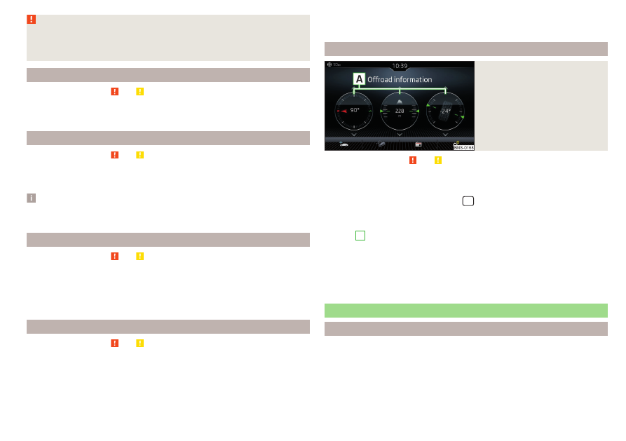
Offroad in Infotainment

Fig. 266 

Offroad Infotainment display

Read and observe   and   on page 219 first.

The display of Offroad mode in Infotainment is used to evaluate the current

driving situation.

To display in the Infotainment menu 



/  Tap on the function surface →

 → Offroad .

A swipe of the finger vertically across the screen allows three of the following

displays 

A

 to be shown 

» Fig. 266

.

Compass (applies to the Amundsen and Columbus Infotainment)

Altimeter (applies to the Amundsen and Columbus Infotainment)

Steering angle display

Coolant temperature display

Oil temperature display

Parking aid (ParkPilot)

Introduction

The parking aid (hereinafter referred to as system) uses acoustic signals or the

Infotainment screen when manoeuvring around obstacles in the vicinity of the

vehicle.

221

Assist systems

-------------------------------------------------------------------------------------------------------------------------------------------------------------

WARNING

Please take note of the general points relating to the use of assistance

systems 

» page 216,

   in section Introduction.

Moving persons or objects may not be recognized by the system sensors.

Under certain circumstances, surfaces of certain objects and types of

clothing cannot reflect the system signals. There is a danger that such ob-

jects or people may not be recognised by the system sensors.

External noise sources may affect the signals of the system sensors.

There is a danger that obstacles may not be detected by the system sen-

sors.

Before reversing, make sure that there are is not any small obstacle, such

as a rock, thin post etc., in front of or behind your vehicle. Such obstacles

may not be recognised by the system sensors.

CAUTION

Keep the system sensors 

» Fig. 267

 on page 222 clean, snow-and ice-free

and do not cover with any objects of any kind, otherwise the system function-

ing may be impaired.

Under adverse weather conditions (heavy rain, water vapour, very low or high

temperatures, etc.), the system function may be limited - “incorrect recogni-

tion of obstacle”.

Accessories fitted to the vehicle rear, such as bicycle carriers, can impair the

system function.

Settings in Infotainment

Read and observe   and   on page 222 first.

In the infotainment system, in menu 



/  tap on function surface  → Park-

ing and manoeuvring.

ParkPilot - Settings for the parking aid

Activate automatically - Activate/deactivate the compact parking aid display

(when driving forward)

Front volume - Adjust the volume of the beeps for obstacle detection in front

Front tone setting - Setting the pitch of the beeps for obstacle detection in

front

Rear volume - Set the volume level of the beeps for the rear obstacle detec-

tion

Rear tone setting - Setting the pitch of the beeps for the rear obstacle detec-

tion

Entertainment fading while parking – Lowers the audio volume (e.g. radio vol-

ume) with activated parking aid

Manoeuvre braking - Activation / deactivation of the automatic emergency

braking

Operation

Fig. 267  Installation location of the sensors on the left side of the vehi-

cle: front / rear

Fig. 268 

Sampled areas and range of the

sensors

Read and observe   and   on page 222 first.

The system uses ultrasound waves to calculate the distance between the

bumper and an obstacle. The ultrasonic sensors are, depending on vehicle

equipment,, located in the back or in the front bumper 

» Fig. 267

.

222

Driving

-------------------------------------------------------------------------------------------------------------------------------------------------------------

Depending on the equipment, the following system versions are possible

» Fig. 268

.

Variant 1: warns of obstacles in areas 

C

D

.

Variant 2: warns of obstacles in areas 

A

B

C

D

.

Variant 3: warns of obstacles in the areas 

A

B

C

D

E

.

Approximate range of sensors (in cm)

Area 

» Fig. 268

Variant 1

(4 sensors)

Variant 2

(8 sensors)

Variant 3

(12 sensors)

A

-

120

120

B

-

60

90

C

160

160

160

D

60

60

90

E

-

-

90

Audible signals

The interval between the acoustic signals becomes shorter as the clearance is

reduced. At a distance of approx. 30 cm a continuous tone starts to sound -

Danger area.
The acoustic signals can be set in Infotainment

» page 222

.

Towing a trailer

When towing, or when another accessory is connected to the trailer socket,

only the areas 

A

 and 

B


» Fig. 268

 are active in the system.

Note

If with Version 3 vehicles not all fields around the vehicle silhouette are ac-

tive after activation the vehicle should be moved forwards or backwards.

The signal tones for front obstacle recognition are factory-set to be higher

than for rear obstacle recognition.

The setting of the acoustic signals is stored (depending on the Infotainment

type) in the active user account personalisation 

» page 59

.

Display in Infotainment screen

Fig. 269 

Screen display

Read and observe   and   on page 222 first.

Function surfaces and warnings 

» Fig. 269

A

Road display.

   Depending on the Infotainment type: Switching off park assistant dis-

play.

Switching audible parking signals on/off.

Disable / enable the automatic emergency braking.

Change to rear-view camera display .

There is an obstacle in the collision area (the distance to the obstacle

is less than 30 cm). 

 Stop moving in the direction of the obstacle!

There is an obstacle in the road (the distance to the obstacle is great-

er than 30 cm).

An obstacle is located outside of the road (the distance to the obsta-

cle is greater than 30 cm).

System failure (there is no indication of obstacles).

Road display

The road display 

A


» Fig. 269

 indicates the road on which the vehicle would

take the current steering wheel and shift / selector lever position.
The shift lever is in the neutral position and the gear selector is in mode N. the

road display is at the front.

223

Assist systems

-------------------------------------------------------------------------------------------------------------------------------------------------------------

Activation / deactivation

Fig. 270 

System key (option 2, 3)

Read and observe   and   on page 222 first.

Activation

The system is activated by engaging the reverse gear, and also by pressing the

 button with vehicles with the versions 2 and 3 or  

» Fig. 270

.

An alarm sounds during activation and the symbol 

 or 

 lights up in the but-

ton.

Deactivation

On vehicles with Version 1, the system can be deactivated by moving out of

reverse gear.
In the case of vehicles with the versions 2 and 3, the system is deactivated by

pressing the button  or  automatically at a speed above 15 km/h (the sym-

bol 

 or 

 goes out in the button).

Fault display

Vehicles with Variant 1

After system activation an acoustic signal sounds for approx. 3 seconds

(there is no obstacle near the vehicle).

Vehicles with the Variants 2 and 3

After system activation, the symbol 

 and 

 flashes in the button.

In the display of the instrument cluster a message about an error of the Park-

Pilot system appears (at the same time there is an audible signal).

Seek help from a specialist garage.

Note

The system can be activated with the key  or  only at a speed below 15

km/h.

Automatic system activation when moving forward

Fig. 271 

Infotainment screen: Display

with automatic activation

Read and observe   and   on page 222 first.

The automatic system activation occurs when moving forward at a speed be-

low 10 km/h when the vehicle approaches an obstacle.
After activation, the following is shown in the left pane of Infotainment display

» Fig. 271

.

Acoustic signals are sounded as of a distance from the obstacle of around

50 cm.
The automatic display can be activated / deactivated in Infotainment

» page 222

.

Note

The setting (activate / deactivate) of the automatic display is stored (depend-

ing on the Infotainment type) in the active user account personalisation

» page 59

.

Automatic emergency braking

Read and observe   and   on page 222 first.

If the system detects a collision risk when travelling forwards or reversing at a

speed up to 10 km/h, there is an automatic emergency braking to reduce the

impact consequences.

Disable / Enable

The brake function can be enabled / disabled in the Infotainment in the menu

Parking and manoeuvring 

» page 222

.

224

Driving

-------------------------------------------------------------------------------------------------------------------------------------------------------------

After switching the ignition on and off, the systems remains activated / deacti-

vated depending on the setting prior to switching off the ignition.
The brake function can also be deactivated once with the function surface 

» Fig. 269

 on page 223.

CAUTION

Automatic emergency braking will only work if the system is engaged by en-

gaging reverse gear or pressing the button  for instance  has been activa-

ted.

Rear traffic alert and wizard for “Blind spot”Monitoring

Introduction

Fig. 272 

Installation location of the radar

sensors

The Rear Traffic Alert and Wizard for “blind spot” monitoring works based on

the information from the radar sensors in the rear bumper 

» Fig. 272

. The radar

sensors are not visible from the outside.

Rear Traffic Alert

The Rear Traffic Alert (hereinafter referred to as system) warns when leaving a

parking space from a transverse parking space about any approaching vehi-

cles.
If necessary, the system tries to avoid a collision with automatic braking, or at

least to mitigate the consequences.

Wizard for “blind spot”monitoring

The wizard for“blind spot monitoring” (hereafter referred to as system) draws

attention to vehicles travelling in the same direction in the next lane in the so-

called blind spots.

The “blind spot” is an area that is not easily visible in a rear-view mirror or even

directly from the vehicle.

WARNING

Please take note of the general points relating to the use of assistance sys-

tems 

» page 216,

   in section Introduction.

WARNING

In the case of a collision or damage to the rear of the vehicle, the function

of the systems may be affected - risk of accident! Have the vehicle

checked by a specialist garage.

Do not cover the sensor area - the function of the systems could be limi-

ted.

Remove snow, ice and such obstacles from the sensor environment im-

mediately.

WARNING

The wizard for “blind spot”monitoring is limited by physical and system-re-

lated limits. Therefore, in the following situations the system can be de-

layed in drawing attention (or not at all) to a vehicle in the next land.

When a vehicle is approaching at a very high speed.

When passing through a very sharp curve or a roundabout.

CAUTION

If a trailer or other accessory is to be connected to the trailer socket, then

the two systems are not available.

In adverse weather conditions (heavy rain, water vapour, very low or high

temperatures, etc.), the system function may be limited - “failure to recognise

a vehicle”.

Accessories additionally installed on the vehicle rear, such as bicycle carriers,

can impair the system function.

225

Assist systems

-------------------------------------------------------------------------------------------------------------------------------------------------------------

Rear Traffic Alert- Operation

Fig. 273  Infotainment screen: warning indicator / driving situation

Read and observe   and   on page 225 first.

With the ignition switched on, the area next to and behind the vehicle is moni-

tored by the radar sensors of the system. If an approaching vehicle is detected

from the rear of the vehicle 

» Fig. 273

, the system warns of this fact.

Warning - vehicles with parking aid

You will hear a continuous tone and one of the following warning levels ap-

pears on the Infotainment screen 

» Fig. 273

.

An oncoming vehicle is detected. Do not continue driving backwards and

check around the vehicle.
A vehicle in the collision region is detected. Do not continue driving back-

wards 

.

Warning - vehicles without parking sensors

An acoustic signal is sounded and information for the driver to observe the

traffic behind is shown in the instrument cluster.

Automatic emergency braking

If the driver does not react to the warning and the system detects an impend-

ing collision, then this can trigger an automatic braking at a speed up to 10

km/h. A corresponding message is shown in the information cluster display.

A

B

Wizard for “Blind Spot”Monitoring - Operation

Read and observe   and   on page 225 first.

At a speed over 15 km/h, the area alongside and behind the vehicle is moni-

tored by the system. At the same time, the distance and the difference in

speed between your vehicle and the other vehicles in the monitored area can

be measured.
When driving, the sensors monitor an area to the left and right to the extent of

a normal lane width.
If a vehicle is detected in the “blind spot” area, the system indicates this vehi-

cle by the indicator light 

 in the exterior mirror.

System limitation

The system is unable to recognise the specific lane width by means of sensors.

Therefore this can e.g. in the following cases respond to a vehicle in a further

lane.

When driving on a road with narrow lanes or on the lane edge.

Driving around a bend.

The system may also respond to objects on the roadside such as crash barri-

ers, noise barriers or similar objects.

Wizard for “Blind Spot”Monitoring - driving situations and warnings

Fig. 274  Driving situation / indicator light in the left outside mirror indi-

cates the driving situation

226

Driving

-------------------------------------------------------------------------------------------------------------------------------------------------------------

Fig. 275  Driving situation / indicator light in the right outside mirror in-

dicates the driving situation

Read and observe   and   on page 225 first.

In the following situations, the indicator light in the outside mirror indicates a

vehicle in the “blind spot”.

Your vehicle 

B

 is being overtaken by vehicle 

A

» Fig. 274

.

Your vehicle 

C

 is overtaking vehicle 

D

 at a speed of max. 10 km high-

er

» Fig. 275

. If the speed during the overtaking is even higher, then there is

no warning by the warning light.

The warning display is always in the exterior mirror on the side of the vehicle

where a vehicle is detected in the “blind spot”.
The greater the speed difference between the two vehicles, the earlier the

warning (by means of the warning light) regarding the vehicle that is overtak-

ing you takes place.

Two warning levels

 light up - a vehicle has been detected in the “blind spot”.

 flash - a vehicle has been detected in the “blind spot” and the turn signal is

switched on.

An advanced warning for vehicles with Lane Assist

 flash also if the steering wheel is turned in the direction of the vehicle in

the “blind spot” . Therefore the Lane Assist 

» page 254

 must be enabled and

the boundary line between the vehicles detected.
If in this case your vehicle indicates crossing the boundary line, with a short vi-

bration of the steering wheel.

Note

The brightness of the indicator light 

 is dependent on the setting of the vehi-

cle lighting. With the low or high beam on the brightness of the light will be

lower.

Activation / deactivation

Read and observe   and   on page 225 first.

The activation or deactivation of the system can be carried out in one of the

following ways.

In the instrument cluster display 

» page 57

Assist systems menu item.

In the infotainment system, in menu 



/  →  → Driver assistance (applies to

the wizard for “blind spot” monitoring).

In the infotainment system, in menu 



/  →  → Parking and manoeuvring (Ap-

plies to Rear Traffic Alerts).

After switching off and switching on the ignition, depending on the setting pri-

or to switching off the ignition, the systems remains activated / deactivated.

Note

When activating the wizard for “blind spot” monitoring, the 

 warning lights

illuminate briefly in the two exterior mirrors.

Malfunctions

Read and observe   and   on page 225 first.

If the systems are not available, an appropriate message appears in the display

of the instrument cluster.

Sensor covered / dirty

If the sensor is dirty or covered, a message indicating that there is no sensor

view appears. Clean or remove the obstructing object from the sensor envi-

ronment 

» Fig. 272

 on page 225.

Systems unavailable

If the systems are unavailable, a message regarding unavailability appears. Stop

the vehicle, switch off the engine and then start it again. If the systems are still

not available, seek the assistance of a specialist garage.

227

Assist systems

-------------------------------------------------------------------------------------------------------------------------------------------------------------

System fault

In the case of a system fault, an error message appears. Seek help from a spe-

cialist garage.

Rear View Camera

Introduction

The rear view camera (following as system) helps the driver when parking and

manoeuvring by displaying the area behind the vehicle in the Infotainment

screen (hereinafter only referred to as screen).
There are four modes available for different situations during the park and ma-

noeuvring action. The mode change is carried out using the function surfaces

on the screen 

» page 229

.

WARNING

Please take note of the general points relating to the use of assistance

systems 

» page 216,

   in section Introduction.

The system displays auxiliary boxes and lines regardless of the current ve-

hicle environment. The driver is responsible for checking that there is no

obstacle in the selected parking space and that the vehicle can safely park

in this space.

The camera may not be soiled or obscured, otherwise the system func-

tion will be significantly affected - there is a risk of accident. For informa-

tion on cleaning 

» page 270

.

CAUTION

The camera image is distorted by contrast with eyesight. For this reason, the

screen display is only of limited use for estimating distances to following vehi-

cles.

Some items, such as thin posts, chain link fences, grilles or uneven road sur-

faces may not be properly displayed in terms of screen resolution.

In a crash or damage the vehicle's rear camera can possibly deviate from the

correct position. If this is the case, have the sensor checked by a specialist ga-

rage.

Note

The camera is equipped with a cleaning system. The spraying is carried out au-

tomatically when the rear window is sprayed.

Function

Fig. 276  Installation location of the camera / scanned area behind the

vehicle

Read and observe   and   on page 228 first.

The camera for capturing the area behind the vehicle is in the grip of the boot

lid 

» Fig. 276

.

Area behind the vehicle 

» Fig. 276

Detection range of the camera
Area outside the detection range of the camera

The system can assist the driver when parking and manoeuvring under the fol-

lowing basic conditions.

The ignition is switched on.
The system is activated.
The luggage compartment lid is completely closed.
The vehicle is travelling at less than 15 km/h.
The area behind the vehicle is clearly visible.
The selected parking / manoeuvring area is clear and even.

A
B

228

Driving

-------------------------------------------------------------------------------------------------------------------------------------------------------------

Activation/deactivation

Fig. 277 

Button for activation / deactiva-

tion

Read and observe   and   on page 228 first.

Activation

The system is activated by selecting reverse gear or pressing the symbol 

button

» Fig. 277

.

When activating, an alarm sounds and the symbol 

 illuminates in the button.

The mode for traverse parking is displayed on the screen.

Deactivation

The system is deactivated when you press button , switch off the ignition,

put the selector lever in position P, or when you drive forwards at a speed of

more than 15 km/h (the 

 symbol in the button goes out).

Functional surfaces

Fig. 278 

Functional surfaces

Read and observe   and   on page 228 first.

It is possible to adjust the parking and manoeuvring mode by means of the

function surfaces.

Function surfaces 

» Fig. 278

Turns off the display of the area behind the vehicle
Mode - traverse parking
Mode - parallel parking
Mode - driving up to a trailer / distance monitoring
Mode - monitor the area behind the vehicle (wide view)
Screen settings - brightness, contrast, colour
Parking aid (thumbnail display)

   Switch thumbnail display on/off

 Switch to full screen display

Orientation lines and lane

Fig. 279 

Orientation and lane lines

Read and observe   and   on page 228 first.

In the modes for transverse and parallel parking guidance, orientation lines for

the assessment of distance and lane lines are displayed on the screen.
Screen display 

» Fig. 279

The distance is about 40 cm (safety distance limit).
The distance is about 100 cm.
The distance is about 200 cm.
The lane lines terminate approximately 300 cm behind the vehicle.

The distance may vary slightly depending on the load of the vehicle and the

road inclination.
The distance between the side lines corresponds approximately to the vehicle

width including mirrors.

A
B
C
D

E
F

G

A
B
C
D

229

Assist systems

-------------------------------------------------------------------------------------------------------------------------------------------------------------

Lane

The lane lines 

D


» Fig. 279

 change depending on the steering angle and indi-

cate the roadway on which the vehicle would take with the current steering

wheel position.

CAUTION

The objects shown on the screen can be closer or even further away than they

appear. This is especially the case in the following situations.

Protruding objects, such as the rear of a truck and the like.

When driving from a horizontal surface into a slope or a depression.

When driving from a slope or a depression onto a horizontal surface.

Mode - traverse parking

Fig. 280  Screen display

Read and observe   and   on page 228 first.

This mode supports the driver when reverse parking in a parking space that is

transverse to the road.

Parking manoeuvre

Select a suitable parking space.

Press the  

» Fig. 277

 on page 229 button.

At the selected parking space 

1

» Fig. 280

 slowly drive past and stop the ve-

hicle.

Engage reverse gear.

Adjust the steering wheel so that the lane lines lead into the parking space

2

.

Carefully move backward and steer so that the yellow lines are still leading

into the parking space.

At the latest when the red line of the back of the parking space (for example,

curb) 

3

 is touched, stop the vehicle.

Mode - parallel parking

Fig. 281  Screen display

Read and observe   and   on page 228 first.

This mode supports the driver when reverse parking in a parking space that is

parallel to the road.

Parking manoeuvre

When driving past a parking space push the button  

» Fig. 277

 on

page 229.

Tap the function surface 

C


» Fig. 278

 on page 229.

The screen shows auxiliary boxes for both road sides.

Switch on the indicator for the side on which you want to park.

The auxiliary boxes for the opposite side will be hidden.

Stop the vehicle stop so that there are no obstructions in the gap between

the auxiliary boxes 

1

» Fig. 281

 and the rear box does not extend over the

side of the parking space 

2

 (e.g. kerb).

Turn the steering wheel in the direction recommended 

3

 until the colour of

the trapezoidal frame 

4

 is green. Hold the steering wheel in this position.

Once the arrow 

5

 appears on the screen, reverse (when reversing in the

parking space the arrow will get shorter).

The screen shows the yellow lane lines 

6

 and the green line 

7

.

If the steering angle is corrected while reversing then the red line 

8

 appears

(required roadway alignment).

230

Driving

-------------------------------------------------------------------------------------------------------------------------------------------------------------

In this case, adjust the steering wheel so that the yellow lines 

6

 the red line

8

 fade into each other.

Carefully reverse until 

 appears on the screen or the green line 

7

 is con-

gruent with the lateral boundary of the parking space (e.g. kerb) 

2

.

Stop the vehicle and steer opposite until the yellow lines 

6

 the red line 

8

fade into each other (required roadway alignment). Hold the steering wheel

in this position.

Orientation lines are displayed 

» Fig. 279

 on page 229 on the screen.

Carefully move backwards.

Stop the vehicle when 

 appears on the screen, or at a safe distance from

the obstacle situated behind the vehicle.

Note

The guidance in the parking space is cancelled due to the system when the

steering wheel is set for a period of time against the required road direction.

The parking is to be started again.

Mode - driving up to a trailer / distance monitoring

Fig. 282 

Screen display

Read and observe   and   on page 228 first.

In this mode, the area behind the vehicle is shown at the top of the screen.

Vehicles with towing hitch

If your vehicle is factory fitted with a tow-bar, this mode supports the driver

when the vehicle approaches a trailer draw bar.
Screen display 

» Fig. 282

Ball head of the towing device
Lines for the distance estimation (at a distance of about 10 cm)

A
B

Line for approaching a trailer draw bar
Trailer draw bar

The line 

C

 moves depending on the steering angle and indicate the roadway

on which the vehicle would take with the current steering wheel position.

Vehicles without towing hitch

If your vehicle is not factory equipped with a towing hitch, a red line for moni-

toring the distance to obstacles is displayed on the screen at a distance of 40

cm behind the vehicle.

Mode - monitor the area behind the vehicle

Read and observe   and   on page 228 first.

In this mode, the area behind the vehicle is shown on the screen.
The mode is suited for the entire view of the situation behind the vehicle.

Area View (AreaView)

Introduction

The area view (below only system) helps the driver when parking and manoeu-

vring by displaying the area around the vehicle on Infotainment screen (below

only screen).
The area around the vehicle is detected by four cameras 

» Fig. 283

 on

page 232.
The system operates in cooperation with the parking aid system. Both systems

are displayed simultaneously on the screen.
For this reason, the chapter on the parking aid is also to be read carefully

and the safety notes are to be observed.

C
D

231

Assist systems

-------------------------------------------------------------------------------------------------------------------------------------------------------------

WARNING

Please take note of the general points relating to the use of assistance

systems 

» page 216

General information.

The system displays auxiliary boxes and lines regardless of the current ve-

hicle environment. The driver is responsible for checking that there is no

obstacle in the selected parking space and that the vehicle can safely park

in this space.

The camera may not be soiled or obscured, otherwise the system func-

tion will be significantly affected - there is a risk of an accident. For infor-

mation on cleaning 

» page 270

.

CAUTION

The camera image is distorted by contrast with eyesight. For this reason, the

screen display is only of limited use for estimating distances to following vehi-

cles.

Objects that are located directly beside the corners of the vehicle may be

outside the field of view of the cameras and may therefore not be displayed on

the screen.

Some items, such as thin posts, chain link fences, grilles or uneven road sur-

faces may not be properly displayed in terms of screen resolution.

In a vehicle damaged in the area of one of the cameras, the respective cam-

era can possibly deviate from the correct position. If this is the case, have the

sensor checked by a specialist garage.

CAUTION

The objects shown on the screen can be closer or even further away than they

appear. This is especially the case in the following situations.

Protruding objects, such as the rear of a truck and the like.

When driving from a horizontal surface into a slope or a depression.

When driving from a slope or a depression onto a horizontal surface.

Operating principle

Fig. 283  Installation locations of cameras for area detection

Read and observe   and   on page 232 first.

The cameras for detecting the area around the vehicle are below the front

ŠKODA logos, in both exterior mirrors and in the handle of the boot lid

» Fig. 283

.

The system can assist the driver when parking and manoeuvring under the

following basic conditions.

The ignition is switched on.
The system is activated.
The driver's door and the luggage compartment lid are fully closed.
The vehicle is travelling at less than 15 km/h.
The areas covered by the cameras are clearly visible on the screen.
The selected parking / manoeuvring area is clear and even.

232

Driving

-------------------------------------------------------------------------------------------------------------------------------------------------------------

Activation / deactivation

Fig. 284 

Button for activation / deactiva-

tion

Read and observe   and   on page 232 first.

Activation

The system is activated by pressing the button  

» Fig. 284

 or by engaging the

reverse gear.
When activating, an alarm sounds and the symbol 

 illuminates in the button.

When activated by pressing the button, the overall view 

» Fig. 285

 on

page 233 -  - is displayed on the screen.
When activated by engaging the reverse gear, the view of the rear camera to-

gether with the thumbnail display of the overall view 

» Fig. 285

 on page 233 -

 - is displayed.

Deactivation

The system is deactivated by pressing  The button, by switching off the igni-

tion, by setting the selector lever to P mode, or by moving forward at a speed

of over 15 km/h (the symbol 

 goes out in the button).

Views and function surfaces

Fig. 285  Overall view / view of the rear camera with thumbnail display

Read and observe   and   on page 232 first.

The system displays the single view of a camera image or the overall view of all

the camera images at once.
The selection of the respective camera image is performed by touching the

screen in the area next to, in front of or behind the vehicle silhouette

» Fig. 285

. The selected area is highlighted on the screen by a yellow framing

» Fig. 285

 - .

Function surfaces 

» Fig. 285

3D views

 Top view

 View obliquely from above

 View from the side

 Change to overall view

Swiping in the arrow directions on the screen, the viewing angle can be

changed to the 3D views of the area around the vehicle.
To exit area view on the display
Display modes
Screen settings - brightness, contrast, colour
Thumbnail display of the overall view (toggle to overall view by touching

the vehicle silhouette on the screen)

   Switch thumbnail display on/off

1

2
3
4
5

233

Assist systems

-------------------------------------------------------------------------------------------------------------------------------------------------------------

CAUTION

The overall view is for orientation only 

» Fig. 285

. Further views of the individu-

al cameras are for a better overview of the area around the vehicle.

View of the rear camera

Read and observe   and   on page 232 first.

The rear camera view is identical to the rear-view camera system 

» page 228

.

View of the front camera

Fig. 286 

Screen display

Read and observe   and   on page 232 first.

View mode of front camera 

» Fig. 286

Traverse parking

The area in front of the vehicle is displayed along with orientation lines

» page 229

Orientation lines and lane

Monitoring of the area in front of the vehicle 

» Fig. 286

The area in front of the vehicle is marked by the blue orientation lines

Top view

The red line marks the distance of about 40 cm from the vehicle

A

B

C

View of the side cameras

Fig. 287 

Screen display

Read and observe   and   on page 232 first.

View mode of the side cameras 

» Fig. 287

Left side
Right side:
Left and right side

The yellow lines are shown at a distance of about 40 cm from the vehicle.

Park Assist

Introduction

Park Assist (following referred to system) helps drivers park in suitable parallel

and perpendicular parking places or also to manoeuvre out of parallel parking

spaces.
The system takes over the steering movements only when parking or leaving a

parking space. The driver operates the brake, accelerator or clutch pedal and

the shift / selector lever.
The state in which the steering wheel is operated by the system, is referred to

as parking operation.
The Park Assist is an extension of the parking aid 

» page 221

 and operates on

the basis of data collected by the ultrasonic sensors.
For this reason, the chapter on the parking aid is to be read carefully and

the safety notes are to be observed.

A
B
C

234

Driving

-------------------------------------------------------------------------------------------------------------------------------------------------------------

WARNING

Please take note of the general points relating to the use of assistance

systems 

» page 216,

   in section Introduction.

During the parking process, the system automatically performs rapid

steering movements. While it is doing so, do not place your hands between

the steering wheel – risk of injury!

During a parking manoeuvre on loose or slippery surfaces (gravel, snow,

ice, etc.) you may stray from the calculated road. It is therefore recommen-

ded that you do not use the system in such situations.

CAUTION

The correct evaluation of the parking space and the parking procedure de-

pends on the circumference of the wheels on the vehicle.

The system only works correctly if the vehicle is fitted with the wheel size

approved by ŠKODA AUTO.

Do not use the system if snow chains or an emergency wheel are fitted.

If wheels other than those approved by ŠKODA AUTO are fitted, the result-

ing position of the vehicle in the parking space can differ slightly. This can be

avoided by readjusting the system at a specialist garage.

CAUTION

If other vehicles are parked behind or on the curb, the system can drive your

vehicle over the kerb or up to the kerb - there is a risk of damage to the

wheels. Intervene in time if necessary.

Note

We recommend performing the parking at a safe speed to about 5 km/h.

The parking procedure can be stopped at any time by pressing the 

» Fig. 288

 on page 235 button or by a steering intervention.

Operation

Fig. 288 

System button

Read and observe   and   on page 235 first.

The system support is provided in the following manner.

While the parking space search is going on, a measurement and evaluation of

the parking space size is completed.

The display of the instrument cluster (hereinafter only display) shows suita-

ble parking spaces and a parking mode is recommended.

The display shows instructions and information before the start and during

the parking.

Based on the calculated road surface, the front wheels will be automatically

rotated during the parking.

Conditions for the system function

The system can look for a parking space only if the following basic conditions

are met.

The system is activated.
The vehicle is travelling at less than 40 km/h.
The vehicle is travelling at less than 20 km/h.
The distance to a number of parked vehicles is approximately 0.5 - 1.5 m.
TCS is activated 

» page 218

.

The system can only carry out the parking procedure if the following basic

conditions are met.

The vehicle is travelling at less than 7 km/h.
The parking procedure takes less than 6 minutes.
There is no driver intervention in the automatic steering operation.
TCS is activated 

» page 218

.

235

Assist systems

-------------------------------------------------------------------------------------------------------------------------------------------------------------

The TCS does not engage.
No trailer or other accessory is connected to the trailer socket.

Activation/deactivation

The system can be activated/deactivated by pressing the  button

» Fig. 288

.

When the system is activated, the 

 symbol illuminates in the button.

Parking space search

Read and observe   and   on page 235 first.

The system searches for a parking space in a number of parallel and transverse

parked vehicles on the passenger or driver's side.

Process with the parking space search

Slowly drive past a row of parked vehicles.

Activate the system with the  button

» Fig. 288

 on page 235.

The system will automatically search for a parking space on the passenger

side.
If the system finds a parking space, the recommended parking mode is dis-

played 

» Fig. 290

 on page 237  or 

» Fig. 291

 on page 237 - .

Activate the turn signal on the driver's side if you wish to look for a parking

space on this side of the road. The display changes and the system searches

for a parking space on the driver's side.

Note

If the symbol  (km / h) is shown in the display while you are looking for a

parking space, the vehicle speed should be reduced below 40 km / hr (parallel

parking) or below 20 km / hr (Transverse parking).

Switch to park mode

Fig. 289  Menus with the parking modes: Display

Read and observe   and   on page 235 first.

While the parking space search is going on and before the start of the parking,

a menu may appear showing other suitable parking modes.
Parking modes 

» Fig. 289

To park backwards in a parallel parking space
To park backwards in a traverse parking space
To park forwards in a traverse parking space

The parking mode can be changed by pressing the  

» Fig. 288

 on page 235

button.
After switching through all parking modes offered, an additional press of the

 button deactivates the system.

If you want to return to the originally recommended parking mode, press the

 button again.

236

Driving

-------------------------------------------------------------------------------------------------------------------------------------------------------------


Content      ..     12      13      14      15     ..