Renault Master (2018 year). Instruction - part 6
1.82
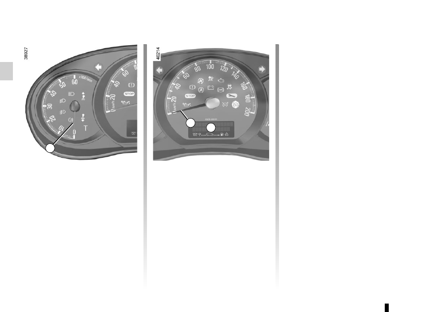
Displays and indicators
(1/2)
Rev counter 1 (graduations ×1000)
Speedometer 2 (mph or km/h)
Overspeed buzzer
Depending on the vehicle, a beep
sounds for 10 seconds approximately
every 40 seconds as long as the vehi-
cle is travelling at over 72 miles per
hour (120 km/h).
2
1
The presence and operation of the display and indicators DEPENDS ON THE LEVEL OF EQUIPMENT AND THE COUNTRY.
Trip computer and warning
system A
Refer to the information on the “Trip
computer and warning system” in
Section 1.
Low engine oil level warning
Depending on the vehicle, when the
engine is started and for 30 seconds,
display A alerts the driver when the
minimum engine oil level is reached.
Refer to the information on the “Engine
oil level” in Section 4.
Fuel level gauge
The number of lit squares on the dis-
play A shows the fuel level. When it is
at the minimum level, the last square
comes on, accompanied by a beep.
The
L
warning light will light up on
the instrument panel.
Fill up as soon as possible.
A