Dacia Pick-Up 1304/1305/1307. Manual - part 105


  Index      Dacia     Dacia Pick-Up 1304/1305/1307 (Engine F8Q) - service repair manual 2004 year


Search            


Content   ..  103  104  105  106   ..


Dacia Pick-Up 1304/1305/1307. Manual - part 105


UPPER FRONT STRUCTURE

42

  42 - 2

FRONT UNIT CARRIAGE BODY

REPLACEMENT

This operation shall be performed only on the repair bench. For the specific supports

mounting on the bench, please see the 40 chapter.

D

ISMO UNTING

Dismount the damaged elements, which are

in contact with the front part body.

Perform a checking redressing on the check-

ing/repairing bench, until bringing the carriage
body almost at the initial shape.

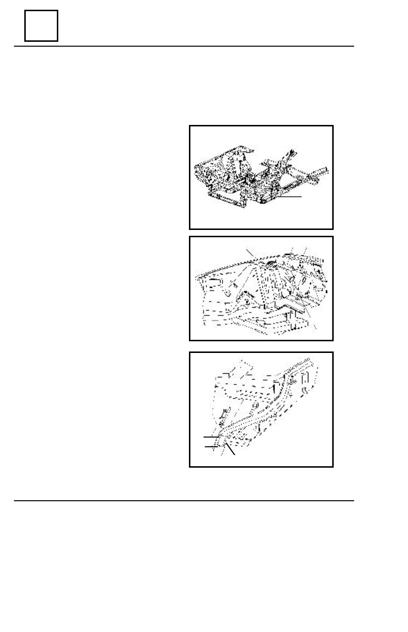
Detach the welding points from to front part

of carriage body as follows :

- in  (2) joining area of the front longitudinal

girders with the pedal floor;

- in  (3) joining area of the front longitudinal

girders with the left / right lateral cross bar;

- in  (4) joining area of the front longitudinal

girders with the intermediary longitudinal girders;

- in  (5) joining area of the front wing

 linings with the iron plate;

- in  (6) joining area of the cover reinforce-

ments and climate control box;

- in  (7) joining area of the front wing

 linings with the front pillar linings;

- in  (8) joining area of the front longitudinal

girder with the iron plate.

Straighten the areas resulted by dismounting.
Grind the areas resulted by dismounting.

R

EMO UNTING

Position and center the new element on the

repairing bench.

Check the correct positioning of the front unit

carriage body.

Weld the front unit carriage body (1) following

the assembling outliners 2,3,4,5,6,7,8,9,10.

Protect the new element with a corrosion

preventing and noise absorbent product.

1

7

6

5

8

4

2

3

42

UPPER FRONT STRUCTURE

  42 - 3

FRONT  WING LINING

REPLACEMENT

This operation shall be performed only on the repair bench. For the specific supports

mounting on the bench, please see the 40 chapter.

D

ISMO UNTING

Dismount the damaged elements, which are in contact with the front wing lining.
Detach the welding points from to the  front wing lining  (1) which are in contact with

:

- the front grill in the (5) area;
- the upper longitudinal girder in (6) area;
- the iron plate in the (3) area;
- the steering cross bar in the (4) area;
- the climate control box in the (2) area.

Straighten the areas resulted by dismounting.
Grind the areas resulted by dismounting.

R

EMO UNTING

Position and center the new element.
Check the correct positioning of the front wing lining.
Weld the front wing lining (1) following the assembling outliners 2,3,4,5,6.
Protect the new element with a corrosion preventing and noise absorbent product.

1

2

2

UPPER FRONT STRUCTURE

42

  42 - 4

HEAD LAMP SUPPORT

D

ISMO UNTING

Dismount the elements, which are in contact with

the headlamp support.

Detach the welding points of  the head lamp (1)

support which are in connection with :

- the radiator upper cross member in the area

(3);

- the reinforcement in the area (4);
- the lower part of the front wing lining in the

area (5);

- the front wing lining in the lateral part in the

(6) area.

Straighten the areas resulted by dismounting.
Grind the areas resulted by dismounting.

R

EMO UNTING

Position and center the new element.
Check the correct positioning of the head lamp

support.

Weld the headlamp support (1) following the

assembling outliners 2,3,4,5,6.

Protect the welding with a corrosion-preventing

product.

Mount the elements, which are connections with

the headlamp support.

1

2

3

4

5

6

42

UPPER FRONT STRUCTURE

  42 - 5

RADIATOR UPPER CROSS MEMBER

D

ISMO UNTING

Dismount the elements, which are in contact with

the radiator upper cross-member.

Detach the welding points of the radiator upper

cross member (2) which are in connection with:

- the head lamp support (7);
- the reinforcement in the  (8) area.

Straighten the areas resulted by dismounting.
Grind the areas resulted by dismounting.

R

EMO UNTING

Position and center the new element.
Check the correct positioning of the radiator upper cross-member.
Weld the tank mask assembly (2) after the assembling outliners 7, 8.
Protect the welds with a corrosion-preventing product.
Mount the elements, which are in connection with the radiator upper cross-member.

7

8


Content   ..  103  104  105  106   ..