Chrysler Cirrus, Dodge Stratus, Plymouth Breeze Haynes. Manual - part 34


  Index      Manuals     Chrysler Cirrus, Dodge Stratus, Plymouth Breeze Haynes (1995-2000). Repair Manual


Search            


Content   ..  32  33  34  35   ..


Chrysler Cirrus, Dodge Stratus, Plymouth Breeze Haynes. Manual - part 34


11-22

Chapter 11

Body

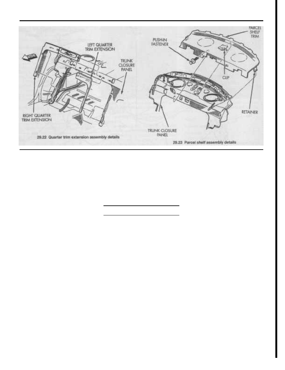
29.22 Quarter trim extension assembly details

LEFT QUARTER

TRIM EXTENSION

RIGHT QUARTER

TRIM EXTENSION

29.23 Parcel shelf assembly details

22

Using a screwdriver, pry off the left and

right quarter panel extensions (see illustra-

tion).

23

Remove the push-in fasteners securing

the parcel shelf to the trunk closure panel

(see illustration).
24

Pull the parcel shelf forward to disen-

gage the clip securing parcel shelf to the

trunk closure panel and remove it from the

vehicle.
25

Remove the two bolts securing the seat

back latch/lock to the trunk closure panel and
remove it from the vehicle.

Installation
26 Installation is the reverse of removal.

Rear seat back latch handle

Removal
27 Inside the trunk, remove the push-in fas-
tener securing the latch handle to the bottom
of the parcel shelf.
28

Detach the handle from the folding rear

seat latch (see illustration 29.5).

Installation
29 Installation is the reverse of removal.

30 Seat belt check

1

Check the seat belts, buckles, latch

plates and guide loops for obvious damage

and signs of wear.
2

See if the seat belt reminder light comes

on when the ignition key is turned to the RUN
or START positions. A warning chime should
also sound.
3

The seat belts are designed to lock up

during a sudden stop or impact, yet allow
free movement during normal driving. Make
sure the retractors return the belt against
your chest while driving and rewind the belt
fully when the buckle is unlatched.
4

If any of the above checks reveal prob-

lems with the seat belt system, replace parts

as necessary.

Chapter 12

Chassis electrical system

Contents

Section

Section

Airbag system - general information..............................................

29

Instrument cluster - removal and installation .................................

20

Antenna - removal and installation .................................................

18

Instrument cluster self-diagnosis ...................................................

19

Bulb replacement ...........................................................................

16

Multi-function switch - check and replacement ............................

8

Circuit breakers - general information ............................................

5

Power door lock system - description and check.........................

26

Cruise control system - description and check .............................

24

Power seats - description and check............................................

28

Compass/temperature Mini-Trip Computer

self-diagnosis............................................................................

30

Power window system - description, check and

window motor replacement......................................................

27

Electric rear view mirrors - description and check ........................

25

Radio, amplifier and speakers - removal and installation..............

17

Electrical troubleshooting ...............................................................

2

Rear window defogger heat grid - check and repair.....................

23

Fuses - general information ...........................................................

3

Rear window defogger switch - check and replacement ..............

22

Fusible links - general information.................................................

4

Relays - general information ..........................................................

6

General information ........................................................................

1

Turn signal/hazard flasher - check, removal and installation .........

7

Headlight assembly - removal and installation ..............................

14

Windshield washer fluid pump - removal and installation .............

10

Headlight switch- check and replacement ....................................

13

Windshield wiper/washer switch - check and replacement..........

9

Headlight and fog light - adjustment .............................................

15

Windshield wiper motor - check and replacement ........................

11

Horn - check, removal and installation ..........................................

21

Wiring diagrams.............................................................................

31

Ignition switch and lock cylinder - removal and installation ..........

12

1

General information

The electrical system is a 12-volt, nega-

tive ground type. Power for the lights and all
electrical accessories is supplied by a
lead/acid-type battery which is charged by
the alternator.

This Chapter covers repair and service

procedures for the various electrical compo-
nents not associated with the engine. Infor-
mation on the battery, alternator, distributor
and starter motor can be found in Chapter 5.
Warning: When working on the electrical sys-
tem, disconnect the negative battery cable
from the ground stud on the left 
shock tower
(see Chapter 5, Section 1) to prevent electri-
cal shorts and/or fires.

2

Electrical troubleshooting

A typical electrical circuit consists of an

electrical component, any switches, relays,

motors, fuses, fusible links or circuit breakers
related to the component and the wiring and

connectors that link the component to both
the battery and the chassis. To help pinpoint
an electrical circuit problem, wiring diagrams
are included at the end of this Chapter.

Before tackling any troublesome electri-

cal circuit, first study the appropriate wiring
diagrams to get a complete understanding of

what makes up that individual circuit. Trouble

spots, for instance, can often be narrowed
down by noting if other components related

to the circuit are operating properly. If several

components or circuits fail at one time,
chances are the problem is in

a

fuse or

ground connection, because several circuits
are often routed through the same fuse and
ground connections.

Electrical problems usually stem from

simple causes, such as loose or corroded
connections, a blown fuse, a melted fusible
link or a bad relay. Visually inspect the condi-
tion of all fuses, wires and connections in a
problem circuit before troubleshooting it.
If testing instruments are going to be utilized,
plan ahead of time where to make the neces-
sary connections to accurately pinpoint the
trouble spot.

The basic tools needed for electrical

troubleshooting include a circuit tester or
voltmeter (a 12-volt bulb with a set of test

12

12-2

Chapter 12 Chassis electrical system

leads can also be used), a continuity tester
(which includes a bulb, battery and set of test
leads) and a jumper wire, preferably with a
fuse or circuit breaker incorporated, which
can be used to bypass electrical components.
Before attempting to locate a problem with
test instruments, use the wiring diagram(s) to
decide where to make the connections.

Voltage checks

Voltage checks should be performed if a

circuit isn't functioning properly. Connect one
lead of a circuit tester to either the negative

battery terminal or a known good ground.

Connect the other lead to a connector in the
circuit being tested, preferably nearest to the

battery or fuse. If the bulb of the tester lights,

voltage is present, which means the part of
the circuit between the connector and the

battery is problem free. Continue checking

the rest of the circuit in the same fashion.
When you reach a point where no voltage is

present, the problem lies between that point

and the last test point with voltage. Most of
the time the problem can be traced to a loose
connection. Note:

Keep

in mind that

some

circuits

receive voltage

only when the ignition

key is in the Accessory

or

Run position.

Finding a short

One method of finding a short in a cir-

cuit is to remove the fuse and connect a test
light or voltmeter in its place to the fuse ter-
minals. There should be no voltage present

in

the circuit. Move the wiring harness from

side-to-side while watching the test light. If

the bulb lights, there's a short to ground

somewhere in that area, probably where the
insulation has rubbed through. The same test
can be performed on each component in the
circuit, even a switch.

"Short finders" are also commonly avail-

able. These reasonably priced tools connect
in place of a fuse and pulse voltage through
the circuit. An inductive meter (included with
the kit) is then run along the wiring for the cir-
cuit. When the needle on the meter stops
moving, you've located the short.

Ground check

Perform a ground test to check whether

a component is properly grounded. Discon-

nect the negative battery cable from the
ground stud on the left shock tower and con-
nect one lead of a self-powered test light,
known as a continuity tester, to a known
good ground. Connect the other lead to the

wire or ground connection being tested. If the

bulb lights, the ground is good. If the bulb
doesn't light, the ground is faulty.

Continuity check

A continuity check is done to determine

if there are breaks in a circuit - if it's capable
of passing electricity properly. With the circuit
off (no power in the circuit), a self-powered
continuity tester can be used to check it.
Connect the test leads to both ends of the
circuit (or to the "power" end and a good
ground) - if the test light comes on the circuit
is passing current properly. If the light does-
n't come on, there's a break (open) some-
where in the circuit. The same procedure can
be used to test a switch by connecting the
continuity tester to the switch terminals. With
the switch on, the test light should come on.

Finding an open circuit

When diagnosing for possible open cir-

cuits, it's often difficult to locate them by
sight because oxidation or terminal misalign-
ment are hidden by the connectors. Merely
wiggling a connector on a sensor or in the
wiring harness may correct the open circuit
condition. Remember this when an open is
indicated when troubleshooting a circuit.
Intermittent problems may also be caused by
oxidized or loose connections. Electrical
troubleshooting is simple if you keep in mind
that all electrical circuits are basically elec-
tricity running from the battery, through the
wires, switches, relays, fuses and fusible
li nks to each electrical component (light bulb,
motor, etc.) and to ground, where it's passed
back to the battery. Any electrical problem is
an interruption in the flow of electricity to and
from the battery.

3

Fuses - general information

Refer

to illustrations 3. la, 3. lb and 3.3

1

The electrical circuits of the vehicle are

protected by a combination of fuses, circuit
breakers and fusible links. One fuse block is
located under a cover on the end of the
instrument panel on the left (driver's) side,
easily accessible by opening the driver's door
(see illustration). A fuse and relay block,
called the Power Distribution Center (PDC) is
located on the left side of the engine com-
partment near the radiator upper support
(see illustration).
2

Each fuse, relay or circuit breaker is

designed to protect a specific circuit. The
various circuits and fuses are identified on
the underside of the PDC or fuse block cov-
ers.
3

Miniaturized fuses are employed in the

fuse block. These compact fuses, with blade
terminal design, allow fingertip removal and
replacement. If an electrical component fails,
always check the fuse first. A blown fuse is

3.1a The interior fuse block is located at

the left end of the instrument panel - open

the driver's door and pull off the cover.

Fuse identification is located on the

underside of the cover

3.1b The Power Distribution Center is located in the engine

compartment and contains both fuses and relays (additional

relays are under the square cover directly above the PDC)

3.3 The fuses used on these models can be checked visually to

determine if they are blown (good fuse on right,

blown fuse on left)

Chapter 12 Chassis electrical system

12-3

4.2 Strip about 1 inch of insulation off both wires, then spread the

strands, push them together and twist them in place

7.1 The turn signal/hazard flasher unit is located in the steering

column and mounted behind multi-function switch

easily identified through the clear plastic
body. Visually inspect the element for

evi-

dence of damage (see illustration). If a con-
tinuity check is called for, the blade terminal

tips are exposed in the fuse body.

4

Be sure to replace blown fuses with the

correct type and rating. Fuses of different rat-
ings are physically interchangeable, but only

fuses of the proper rating should be used.

Replacing a fuse with one of a higher or lower

value than specified is not recommended.

Each electrical circuit needs a specific

amount of protection. The amperage value of
each fuse is molded into the fuse body.
5

If the replacement fuse immediately

fails, don't replace it again until the cause of
the problem is isolated and corrected. In

most cases, the cause will be a short circuit
in the wiring caused by a broken or deterio-

rated wire.

4

Fusible links - general
information

Refer to illustration 4.2
1

The circuit from the output terminal of

the Power Distribution Center to the alterna-
tor and the starter motor (1995 and 1996
vehicles with manual transaxles only) is pro-
tected by a wire called a fusible link. Fusible
li nks are used in circuits which are not ordi-
narily fused, such as the starting or ignition
circuit(s).
2

Although the fusible links appear to be a

heavier gauge than the wires they're protect-
ing, the appearance is due to the thick insula-
tion. All fusible links are four wire gauges
smaller than the wire they're designed to pro-
tect. Fusible links cannot be repaired, but a
new link of the same amperage rating can be
installed. The procedure is as follows:

a) Disconnect the negative cable from the

remote battery terminal.

b) Disconnect the fusible link from the

component at the eyelet terminal con-
nection.

c) Cut the damaged fusible link out of the

wiring just behind the crimp connector.

d) Strip the insulation back approximately

1-inch.

e) Spread the strands of the exposed wire

apart, push them together and twist

them in place (see illustration). Note: If

available, this connection may be made
using another crimp type connector.

Use rosin core type solder and solder
the wires together to obtain a good con-

nection.

Use plenty of electrical tape around the

soldered joint. No wires should be
exposed.

h) Connect the new fusible link eyelet ter-

minal to the component and tighten the
screw 
securely.

i) Connect the negative cable to the

remote battery terminal. Test the circuit
for proper operation.

5

Circuit breakers - general

information

Circuit breakers protect components

such as power windows, power door locks,
power seats and sunroof (if equipped). The
circuit breakers are located in the fuse block.
On some models the circuit breaker resets
itself automatically, so an electrical overload
in the circuit will cause it to fail momentarily,
then come back on. If the circuit doesn't
come back on, check the circuit breaker
immediately (some circuit breakers must be
reset manually). If the circuit breaker blows
again, check the circuit for a short and cor-
rect it as soon as possible. Once the condi-

tion is corrected, the circuit breaker should

resume its normal function.

6

Relays - general information

Several electrical circuits in the vehicle

that draw heavy amperage utilize relays to
transmit current to the component. If the
relay is defective, the component won't oper-
ate properly. Relays are located in the fuse
block and the Power Distribution Center (see
illustrations 3.1a and 3.1b).

If a faulty relay is suspected, it can be

removed and tested by a dealer service
department or other qualified repair shop.
Defective relays are not serviceable and must
be replaced as a unit. Note: Checks for the

starter, automatic shutdown and fuel pump
relays are located in 
Chapter 4.

7

Turn signal/hazard flasher -
check, removal and installation

Warning: These models have airbags. Always
disable the airbag system before working in
the vicinity of the impact sensor, steering col-
umn or instrument panel to avoid the possibil-
ity of accidental deployment of the airbag,
which could cause personal injury 
(see Sec-
tion 29).

Check

Refer to illustration 7.1
1

The turn signal/hazard flasher is a small

unit located behind the multi-function switch
inside the steering column (see illustration).
2

When the flasher unit is functioning

properly, an audible click can be heard during
its operation. An inoperative or incomplete
turn signal circuit will result in an increased
flasher speed.
3

If both turn signals fail to blink, the prob-

lem may be due to a blown fuse, a faulty
flasher unit, a broken switch or a loose or

f)

g

)

12

12-4

Chapter 12 Chassis electrical system

8.3 Multi-function switch terminal guide and continuity chart

SWITCH POSITI0N

MODE

CONTINUITY

BETWEEN

TURN SIGNAL with

HAZARD WARNING

SWITCH OFF

RIGHT

A-1 and B-6

LEFT

A-1 and B-7

TURN SIGNAL

with

HAZARD WARNING

SWITCH ON

RIGHT

or

OFF

or

LEFT

A-1 and B-6

A-2 and A-5
A-1 and B-7

B-6 and B-7

HEADLAMP BEAM

ON

PARK

C-2 and C-1

LOW

C-2 and C-1

C-4 and C-7

HIGH

C-2 and C-1

C-4 and C-8

PANEL DIMMER

DETENT

1

2

to 8

9

A-2 and C-6

<100Ω

300 to 2630

LINEAR

4.99k to 10.5k

Ω

OPTICAL HORN

ON

C-4 and C-8

FRONT FOG

ON

C-9 and C-10

WIPER

INT

DETENT

1

2

3

4

5
6

B-3 and B2

11.87kΩ

9.87k 

7.87kΩ

5.87k

Ω

3.87k
1.87k

Ω

LOW

B-3 and B-2

1.25k

Ω

HIGH

B-3 and B-2

1.82k

MIST

ON

B-3 and B-2

1.25k

Ω

WASHER

ON

B-3 and B-1

COMB0-FLASHER-A

7-WAY CONNECTOR-B

10-WAY CONNECTOR-C

open connection. If a quick check of the fuse
box indicates the turn signal fuse has blown,
check the wiring for a short before installing a
new fuse.
4

If the fuse is OK, remove the turn signal

li ght bulbs and make sure they are opera-
tional by attaching them to a 12 volt power
source.
5

If the bulbs check out OK, check the

turn signal section of the multi-function
switch (see Section 8). Also check the wiring
harness continuity.

Removal

6

To replace the flasher, remove the steer-

ing wheel column covers (see Chapter 11).
7

Locate the turn signal/hazard combo-

flasher (black relay) behind the multi-function

switch (see illustration 7.1).
8

Pull the flasher unit out of the multi-

function switch.

Installation

9

Make sure the replacement flasher unit

is identical to the original. Compare the old

one to the new one before installing it.

10 Install the flasher unit into the multi-

function switch making sure it is fully seated.

11

Install the steering wheel column covers

(see Chapter 11).

8

Multi-function switch - check and

replacement

Warning: These models have airbags. Always
disable the airbag system before working in
the vicinity of the impact 
sensor, steering col-
umn or instrument panel to avoid the possibil-
ity of accidental deployment of the 
airbag,
which could cause personal injury (see Sec-
tion 29).
1

The multi-function switch is located on

the steering column. It incorporates the turn
signals, hazard warning, headlights, headlight
beam select (HI/LO), headlight flasher, instru-
ment panel dimmer switch, fog lights, wind-
shield wiper and windshield washer func-
tions. There are two levers on the multi-func-
tion switch, the left side controls the signaling
and lighting, the right side controls the wipers
and washer system.

Check

Refer to illustration 8.3
2

Remove the multi-function switch from

the steering column and remove the flasher

unit from the switch (see below).

3

Using an ohmmeter or a continuity

tester, refer to the accompanying chart and
check for continuity between the switch ter-

minals with the switch in each position (see
illustration). 
If any portion of the switch is

faulty, the entire multi-function switch assem-

bly must be replaced.

4

After the check is complete, replace the

flasher unit and install the multi-function
switch onto the steering column (see below).

8.7 Multi-function switch mounting

screws (arrows)

Replacement

Refer to illustration 8.7
5

Remove the steering column covers

(see Chapter 11).
6

Disconnect the electrical connectors

from the back side of the switch.
7

Remove the 2 mounting screws and

detach the switch from the steering column
(see illustration).
8

Installation is the reverse of removal.

9

Windshield wiper/washer switch

- check and replacement

Warning: These models have airbags. Always
disable 
the airbag system before working in

the vicinity of the impact sensor, steering col-

umn or instrument panel to avoid the possibil-
ity of accidental deployment of the airbag,

which could cause personal injury (see Sec-

tion 29).

Chapter 12 Chassis electrical system

12-5

10.7 Windshield washer pump (arrow) is

located in the reservoir

1

The wiper/washer switch is part of the

multi-function switch, refer to Section 8 for

check, removal and installation procedures.
2

If the wipers do not operate, check the

windshield wiper motor (see Section 11).

10 Windshield washer fluid pump -

removal and installation

Removal

Refer

to illustration 10.7

1

If the washer reservoir contains fluid,

siphon it into a suitable container.
2

Detach the washer fluid hose at the in-

li ne connector on top of the right shock
tower.
3

Remove the front bumper (see Chap-

ter 11).
4

Remove the EVAP carbon canister (see

Chapter 6).
5

Disconnect the electrical connector

from the washer pump.
6

Detach the washer hose from the reser-

voir.
7

Remove the mounting screws and

maneuver the reservoir (with pump attached)
from the vehicle (see illustration).
8

To remove the washer pump, simply

grasp the pump and using a twisting motion
pull the pump out of the reservoir grommet.

Installation

9

Installation is the reverse of removal. If

the pump was removed, install a new grom-

met.

11 Windshield wiper motor - check

and replacement

Check

Refer

to illustration 11.3

1

If the wipers do not operate at all, check

the fuses (see Section 3).
2

If the fuses are OK, remove the cowl

11.3 Windshield wiper motor electrical

connector terminal identification

1

Wiper

park switch

2

Ground

3

Wiper

switch low

speed

4

Wiper

switch high speed

cover (see Chapter 11) to access the wiper
motor electrical connector. Make sure the
terminals are clean and tight. Turn the ignition
switch and wiper switch on. Recheck the
wiper operation.
3

If the wipers still do not operate, discon-

nect the electrical connector and connect a
voltmeter to terminal no. 2 (-) and 4 (+) (see
illustration). 
Turn the ignition switch On and
the wiper switch to the HI position - voltage
should be indicated. Connect the voltmeter
to terminal no. 2 (-) and 3 (+), place the wiper
switch in the LO position - voltage should be
indicated. If no voltage is indicated in either
position, check for continuity between termi-
nal no. 2 and ground, if no continuity is indi-
cated, repair the ground connection.
4

If voltage is present in the HI and LO

positions, remove the motor and check it off
the vehicle with fused jumper wires con-
nected to the battery remote terminals. If the
motor now operates, check for binding link-
age. If the motor still does not operate,
replace it.
5

If there's no voltage at the motor electri-

cal connector, the problem is in the switch,

the wiper relays, the Body Control Module

(BCM) or the related wiring. Check the wiper
switch (see Section 9) and, if necessary, per-

form continuity tests on the wiring. Have the

BCM checked by a dealer service depart-
ment or other properly equipped repair shop.

Replacement

Refer

to illustrations 11.8a, 11.8b and 11.11

6

Disconnect the negative battery cable

from the ground stud on the left shock tower

(see Chapter 5, Section 1).
7

Remove the cowl cover (see Chap-

ter 11).
8

Remove the wiper motor/linkage assem-

bly mounting bolts (see illustrations).
Remove the wiper motor/linkage assembly.

9

Disconnect the wiper motor electrical

connector and harness clip from the forward

11.8a Wiper motor/linkage mounting bolts

(arrows) - left side

11.8b Wiper motor/linkage mounting bolt

(arrow) - right side

mounting leg.
10

To remove the linkage from the motor

crank, insert a screwdriver between the crank
and the linkage, then twist the screwdriver
and lift straight up on the linkage to separate
the ball cap from the ball.
11

Remove the motor retaining nuts (see

illustration) and separate the motor from the
li nkage assembly.
12 Installation is the reverse of removal.

11.11 Wiper motor mounting

nuts (arrows)

12

12-6

Chapter 12 Chassis electrical system

12.6 Remove the ignition switch

mounting screw

12 Ignition switch and lock cylinder

- removal and installation

Warning: These models have airbags. Always
disable the airbag system before working in

the vicinity of the impact sensor, steering col-

umn or instrument panel to avoid the possibil-
ity of accidental deployment of the airbag,
which could cause personal injury 
(see Sec-
tion 29).

1

When the ignition switch is in the

RUN/START position, it connects power from

the Power Distribution Center (PDC) to the
fuel pump relay, starter motor relay, Power-
train Control Module, ABS control module
and distributor (V6 engine).

Ignition switch

Removal

Refer to illustration 12.6
2

The ignition switch is located inside the

steering column and is activated by, and
attached to, the key lock cylinder.
3

Disconnect the negative battery cable

from the ground stud on the left shock tower
(see Chapter 5, Section 1).
4

Remove the steering column covers

(see Chapter 11).
5

Remove the key lock cylinder (see

below).

6

Remove the screw securing the switch

to the steering column (see illustration).
7

Depress the retaining tabs, then detach

the switch and lower it from the steering col-
umn.
8

Disconnect the electrical connector

from the ignition switch.

Installation

9

Installation is the reverse of removal.

Make sure the switch and lock cylinder are in
the RUN position before installation. Tighten
the switch mounting screw securely.

Lock cylinder

Removal

Refer to illustration 12.14
10

The ignition key lock cylinder is located

12.14 To remove the lock cylinder, place

the ignition key in the RUN position and

use a small screwdriver to depress the

spring loaded retaining tab, then pull the

lock/key out of the housing

on the right side of the steering column.
11

Disconnect the negative battery cable

from the ground stud on the left shock tower

(see Chapter 5, Section 1).
12

Remove the steering column covers

(see Chapter 11).

13 Insert the ignition key and turn the

switch to the RUN position.

14

Depress the retaining tab with a small

screwdriver and then withdraw the lock cylin-
der from the housing (see illustration).

Installation

Refer to illustration 12.15
15

Make sure the slot in the ignition switch

is in the RUN position (see illustration) and
insert the lock cylinder into the housing until
the retaining tab locates the housing. Check
key operation.
16

The remaining installation steps are the

reverse of removal.

13 Headlight switch - check and

replacement

Warning: These models have airbags. Always
disable the airbag system before working in
the vicinity of the impact 
sensor, steering col-
umn or instrument panel to avoid the possibil-
ity of accidental deployment of the airbag,

12.15 Make sure the ignition switch

mating slot located inside the housing

(arrow) is in the RUN position before

installing the lock cylinder

which could cause personal injury (see Sec-

tion 29).

1

The headlight switch is part of the multi-

function switch, refer to Section 8 for check,

removal and installation procedures.

14 Headlight assembly - removal

and installation

Warning: The headlight bulbs are gas-filled
halogen type and under 
pressure. If the sur-
face is scratched or the bulb is dropped it
may shatter. 
Wear eye protection and handle
the bulbs carefully, grasping only the 
base
whenever possible. Don't touch the surface
of the bulb with your fingers 
because the oil
from your skin could 
cause it to overheat and
fail prematurely. If you happen to touch the
bulb surface, clean it with rubbing alcohol.

Removal

Refer to illustrations 14.1 and 14.3
1

Open the hood and remove the head-

light mounting screws (see illustration).
2

To protect the body paint, place a soft

piece of thin material such as a credit card or
cardboard between the headlight assembly
and the front fender.

3

Using a screwdriver applied between

the cardboard (or equivalent) and the head-

14.1 Headlight mounting

and adjustment details

1

Headlight assembly
mounting screws

2

Vertical position

adjusting screw

3

Vertical position

indicator (bubble level)

4

Horizontal position
indicator/adjuster

Chapter 12 Chassis electrical system

12-7

15.4 Headlight vertical

position indicator - Do

not tamper with the

screw located on the

indicator or calibration

will be lost. When

properly adjusted, the

bubble should be in the

range shown

ACCEPTABLE -

RANGE

.75 O UP

TO

.75 O DOWN -

BUBBLE

LEVEL

14.3 While protecting the body paint with padding

placed between the screwdriver and the fender, use a

screwdriver to carefully pry the headlight assembly from

the ball socket (arrow)

li ght assembly, carefully pry the headlight
assembly away from the fender to disengage
it from the ball socket (see illustration).
4

Disconnect the electrical connectors

from the headlight and park/turn signal bulb
holders and remove the headlight assembly
from the vehicle.

Installation

5

Installation is the reverse of removal.

Make sure the electrical connectors are
securely attached. Adjust the headlights if
necessary (see Section 15).

15

Headlight and fog light -

adjustment

Warning: The headlights must be aimed cor-
rectly. If adjusted incorrectly, they could tem-
porarily blind the driver on an oncoming vehi-
cle and cause an accident or seriously reduce

your ability to see the road. The headlights

should be checked for proper aim every 12
months and any time a new headlight is
installed or front end body work is performed.
The following procedure is only an interim
step to provide temporary adjustment until
the headlights can be adjusted by a 
dealer
service

department

or other properly

equipped shop.

Headlights

Using the built-in indicators
Refer to illustrations 15.4 and 15.6
1

The headlight assemblies have built-in

horizontal and vertical position indicators
which are calibrated at the factory.
2

Adjustment should be made with the

vehicle on a level surface, with a full gas tank
and a normal load in the vehicle.
3

Rock the vehicle side-to-side three

ti mes, then push down on the front bumper
to jounce the front suspension up-and-down
three times. This will allow the suspension to
stabilize prior to adjustment.
4

Open the hood and check the vertical

indicators on the headlight assemblies. The
bubble in the vial should be centered over the

zero (see illustration). Note: A bubble
located anywhere between 0.75 degrees UP
and 0.75 
degrees DOWN is also acceptable.

5

If the bubble is not within the 0.75

degrees UP to 0.75 degrees DOWN range,
adjust the vertical aiming screw (see illustra-
tion 15.1) 
as required to bring the bubble
back to the centered location. Caution: Do
not tamper with the screw on the vial itself or
calibration will be lost.
6

Next, check the horizontal indicators.

The arrow on the adjuster should be pointing
to the zero mark on the gauge wheel (see
illustration).
7

If the arrow is not pointing to the zero

mark, adjust the horizontal aiming screw (see
illustration 15.6) 
as required to align the hor-
izontal marks.

Using an alignment screen
Refer to illustration 15.13
8

This procedure requires a level surface

and a flat blank wall with room to park the
vehicle 25 feet from the wall.
9

Position a masking tape line vertically on

the wall in reference to the centerline of the

vehicle and the headlights. Note: It may be

easier to position the tape on the wall with the

vehicle parked only a few inches away, then

move the vehicle directly backwards away
from the wall.

10

With the vehicle 25 feet away from the

wall, rock the vehicle side-to-side three times,
then push down on the front bumper to
jounce the front suspension up-and-down
three times. This will allow the suspension to
stabilize.

15.6 Headlight horizontal position

indicator - When properly adjusted, the

arrow on the adjuster should be pointing

to the zero mark on the gauge wheel

11

Measure the distance from the floor to

the centerline of each headlight lens. Transfer
these dimensions to the wall and place
another masking tape line horizontally at
each location.
12

Measure the distance from the center-

li ne of each headlight lens to the center of the
vehicle. Transfer these dimensions to the flat
wall on each side of the vertical centerline
tape line and place a masking tape line verti-
cally at each location.
13

On the wall at the left headlight location,

place a 2 inch square piece of tape 8 inches
below the horizontal line and 5 inches to the
right of the vertical centerline. This is the target
spot for the left headlight (see illustration).

Vehicle

Headlight

Centerline

Centerline

15.13 Headlight beam

adjusting details using an

alignment screen

12


Content   ..  32  33  34  35   ..