Chrysler Cirrus, Dodge Stratus, Plymouth Breeze Haynes. Manual - part 32


  Index      Manuals     Chrysler Cirrus, Dodge Stratus, Plymouth Breeze Haynes (1995-2000). Repair Manual


Search            


Content   ..  30  31  32  33   ..


Chrysler Cirrus, Dodge Stratus, Plymouth Breeze Haynes. Manual - part 32


11-6

Chapter 11

Body

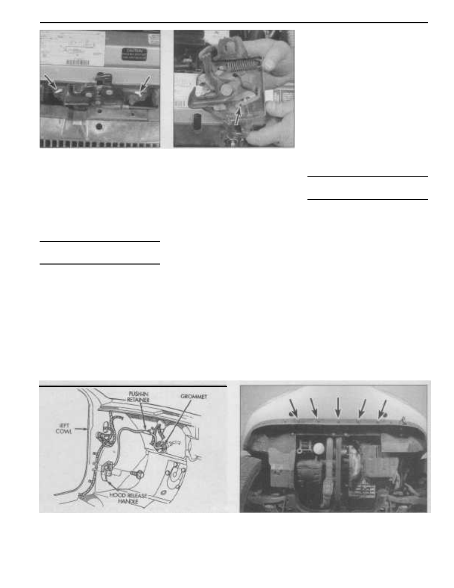
10.2 For a reference point at installation,

mark the position of the hood latch

on the radiator support

alignment marks around the hood latch
assembly before loosening the mounting

nuts.
13

The hood latch assembly, as well as the

hinges, should be periodically lubricated with

white lithium-base grease to prevent sticking
and wear.

10

Hood latch and cable - removal

and installation

Warning: These models have airbags. Always
disable the airbag system before working in
the vicinity of the impact 
sensors, steering
column or instrument panel to avoid the pos-
sibility of accidental deployment of the
airbag, which could 
cause personal injury
(see Chapter 12).

Latch

Removal
Refer to illustrations 10.2 and 10.3
1

Open the hood and support it on the

prop rod.
2

Scribe alignment marks around the

hood latch assembly to aid alignment during

10.3 Slide the cable housing from the

key-hole slot in the hood latch, then slide

the cable through the slot (arrow) in the

release arm and separate the cable

from the hood latch assembly

installation (a permanent-type felt-tip marker
or paint will also work for this) (see illustra-

tion).

3

Remove the nuts and detach the latch

assembly from the radiator support, then dis-

connect the release cable from the hood

latch assembly (see illustration).

Installation

4

Installation is the reverse of removal.

Align the hood latch assembly with the marks
on the radiator support and then tighten the

nuts. Check hood latch operation. Readjust

as necessary.

Cable

Removal

Refer to illustration 10.8
5

Disconnect the release cable from the

hood latch (see Steps 1 through 3).
6

Detach the cable from the clips securing

it to the radiator support.
7

Inside the vehicle, remove the left front

kick panel to gain access to the hood release
handle bolts.

8

Remove the bolts securing the hood

release handle/cable assembly to the cowl
panel (see illustration).
9

Under the dash, locate and disengage

the push-in retainer and cable grommet from
the firewall.
10

Connect a piece of heavy string or flexi-

ble wire to the engine compartment end of
the cable, then from inside the vehicle, pull
the cable with string or wire attached through
the firewall into the vehicle. Disconnect the
string or wire from the old cable.

Installation
11

Connect the string or wire to the new

cable and carefully pull it through the firewall
into the engine compartment.
12

The remaining installation steps are the

reverse of removal.

11

Radiator grille (Cirrus models) -
removal and installation

Warning: These models have airbags. Always
disable the 
airbag system before working in
the vicinity of the impact sensors, steering
column or instrument panel to avoid the pos-

sibility of accidental deployment of the
airbag, which could 
cause personal injury

(see Chapter 12).

Removal

1

Open the hood and support it on the

prop rod.
2

Remove the front bumper with grille

attached (see Section 12).

3

Using an appropriate size drill, remove

the rivets securing the grille to the bumper
and separate the grille from the bumper.

Installation

4

Installation is the reverse of removal.

The grille can be reattached to the bumper

using rivets (if available) or screws, nuts and

washers. If threaded fasteners are used,
apply thread locking compound to the screw
threads.

10.8 Hood release cable and handle details as viewed

from inside the vehicle

12.5 Remove the five push-in fasteners (arrows) securing the

bottom of the front bumper to the radiator lower support

Chapter 11 Body

11-7

12.7 To remove the push-in fasteners, pry out the center

stud and then remove the outer housing

12.8 Front bumper assembly details

12 Bumpers - removal and

installation

Warning: These models have airbags. Always
disable the airbag system before working in

the vicinity of the impact sensors, steering

column or instrument panel to avoid the pos-
sibility of accidental deployment of the
airbag, which could cause personal injury

(see Chapter 12).

Front bumper

Removal

Refer to illustrations 12.5, 12.7, 12.8 and 12.9

1

Open the hood and support it on the

prop rod.

2

Disconnect the negative battery cable

from the ground stud on the left shock tower
(see Chapter 5, Section 1).
3

Remove the fasteners securing the front

fender inner splash shields to the lower sec-
tion of the bumper.

4

Pull the splash shields away from the

fender well

as

necessary to remove the bolts

securing the bumper to the front fender.
5

Remove the push-in fasteners securing

the bottom of the bumper to the radiator
lower support (see illustration).
6

If equipped, disconnect the foglight

wiring harness connectors.
7

Remove the push-in fasteners securing

the bumper (and grille on Cirrus models) to
the radiator upper support (see illustration).
8

Disengage the bumper from the hooks

on the front fenders (both sides) and remove
the bumper from the vehicle (see illustra-

tion). Note: If you are performing this job
alone, place some blankets or other suitable
padding on the ground below the bumper to
protect the paint should the bumper fall dur-
ing removal.

9

If required, the bumper reinforcement bar

can be removed at this time (see illustration).

Installation

10 Installation is the reverse of removal.

Rear bumper

Removal

Refer to illustration 12.13

11

Open the trunk lid.

12

Remove the left rear tail lamp and dis-

connect the license plate light wiring from the
tail lamp assembly.

13

On Cirrus models, remove the right rear

tail lamp. Working inside the tail lamp cavi-
ties, remove the push-in fasteners securing
the bumper to each rear quarter panel (see
illustration).

14

Remove the push-in fasteners securing

the trunk lid slam pads to the rear bumper
and the center of the bumper to the rear clo-
sure panel.

15

Remove the screws holding bumper to

each rear wheel well splash shield.

16

Remove the bolts securing the bumper

to the rear quarter panel in each wheel well.
17

Slide the bumper rearward to disengage

the hooks securing it to the bottom of each
quarter panel and remove it from the vehicle.

12.9 To detach the front bumper bar, disconnect the battery

temperature sensor electrical connector and remove the

three bolts (arrows) at each end of the bar

12.13 Rear bumper assembly details

11

11-8

Chapter 11 Body

13.2 If you don't have a window crank

removal tool (which is available at most

auto parts stores and relatively

inexpensive), place a shop cloth behind the

window crank handle and work it back-

and-forth to dislodge the retaining clip

Note: If you are performing this job alone,

place some blankets or other suitable
padding on the ground below the bumper to
protect the paint should the bumper fall dur-
ing removal.

18 If required, the bumper reinforcement

bar can be remove at this time, however,
before removal use a felt tip pen to mark the
position of the nuts on the bar to aid with
installation.

13.3 Carefully pry off the speaker grille

13.4 Remove the 3 screws (arrows) that

secure the panel to the door

Installation

19 Installation is the reverse of removal.

13 Door trim panel - removal and

installation

Removal

Refer to illustrations 13.2, 13.3, 13.4, 13.5a,

13.5b, 13.6, 13.7, 13.8, 13.9 and 13.11

Note: This procedure applies to both the
front and rear 
doors.
1

Open door and completely lower win-

dow glass.
2

On manual window models, remove the

window crank using a special tool (available

13.5a Pry off the screw cover in the

pull handle area .. .

at most auto parts stores) or by working a
cloth back-and-forth behind the handle to
dislodge the retaining clip (see illustration).
3

Carefully pry off the speaker grille (see

illustration).
4

Inside the speaker opening, remove the

three screws securing the trim panel to the
door (see illustration).
5

On the pull handle, pry off the screw

cover and remove the screw (see illustra-
tions).
6

Pry the screw cover from the door han-

dle latch trim and remove the screw (see
illustration).

13.5b . . . and remove the screw

7

Remove the screw securing the door

trim panel near the upper door hinge (see
illustration).
8

Carefully pry around the door trim panel

to disengage it from the retaining clips (see

illustration).
9

Grasp the trim panel and pull up sharply

to detach it from the retainer channel in win-

dow sill (see illustration).
10

Position the trim panel slightly away

from the door and disengage the clip holding
the door latch linkage to the door handle.

11

On models so equipped, disconnect the

electrical connectors from the speaker,

13.6 Pry off the screw cover in the door
latch handle trim and remove the screw

13.7 Remove the door trim panel screw

near the upper door hinge

13.8 Carefully pry around the door panel

to disengage it from the retaining clips

Chapter 11 Body

11-9

13.9 Grasp the door trim panel and lift it up sharply to detach it

from the retainer channel in the window sill, then separate it from

the door just far enough to disconnect the electrical connectors

13.11 Disconnect the outside mirror electrical connector

from the door trim panel

14.4a Front door latch assembly details

REAR

DOOR

LATCH

LI NKAGE

BELL CRANK-

14.4b Rear door latch assembly details

power door lock switch, the mirror switch
and power window switch (see illustration)
and then remove the trim panel. Caution: Do

not allow the trim panel to hang from the
electrical wires.

14.6 Door latch mounting screws (arrows)

- "A" indicates the latch adjustment slot

(front door shown)

Installation

12

Reconnect any electrical connectors

and install the latch linkage into the door han-
dle. Secure it with the retaining clip.
13

Engage the top of the trim panel into the

window sill retainer channel and press it into
place and seating all clip fasteners.
14

The remaining installation steps are the

reverse of removal.

14 Door latch, outside handle and

lock cylinder - removal,

installation and adjustment

Note: This procedure applies to both the
front and rear doors.

Latch

Removal

Refer to illustrations 14.4a, 14.4b and 14.6
1

Remove the door trim panel (see Sec-

tion 13), except on vehicles equipped with
electric windows, close the window before

disconnecting the door trim panel electrical
connectors.
2

On vehicles with manual windows,

install the window crank (without the retaining
clip) and roll up the window.
3

If you are removing a rear door latch,

remove the window glass lower rear run
channel.
4

Disconnect the lock cylinder, lock but-

ton and latch release operating rods from the
door latch (see illustrations).
5

On vehicles equipped with power door

locks, disconnect the electrical connector
from door lock motor.
6

Remove the three mounting screws

from the end of the door and remove the
door latch (see illustration).

Installation

7

Place the latch in position, install the

screws and tighten them securely.
8

Connect the operating rods to the latch

and secure with retaining clips. Caution: Do
not close the door until the latch has been

properly adjusted (see below) it may not

reopen.

11

14.21 Door lock assembly details

15.2 Remove the plastic water shield from the door

11-10

Chapter 11 Body

GASKET

Adjustment

9

Insert a hex-wrench through the elon-

gated hole in the end of the door near the
latch (see illustration 14.6).

10

Engage the wrench in the socket head

screw located on the side of the door latch
li nkage and loosen it a couple of turns.

11

Lift the outside door handle all the way

up and then release it.

12

Tighten the socket head screw on the

door latch linkage and check door operation.

Outside handle

Removal

13

Remove the door trim panel (see Sec-

tion 13), except on vehicles equipped with
electric windows, close the window before
disconnecting the door trim panel electrical
connectors.

14

On vehicles with manual windows,

install the window crank (without the retaining

clip) and roll up the window.

15

On vehicles equipped with the Vehicle

Theft Security System (VTSS), remove the

disarming switch from the door handle.

16

Disconnect the operating rod, remove

the mounting nuts and withdraw the handle
from the door.

Installation

17 Installation is the reverse of removal.

Lock cylinder

Removal

Refer to illustration 14.21

18

Remove the outside door handle (see

Steps 13 through 16).

19

Detach the operating rod retaining clip

and operating rod from the lock cylinder.
20

On vehicles equipped with the Vehicle

Theft Security System (VTSS), remove the

ill uminated entry switch wiring clip and dis-
connect the electrical connector.

21

Using a screwdriver, pry the lock cylin-

der retainer off and withdraw it from the door
(see illustration).

Installation

22 Installation is the reverse of removal.

15 Door window glass - removal and

installation

Note: This procedure applies to both the
front and rear doors.

Removal

Refer to illustrations 15.2, 15.3, 15.4 and 15.9

1

Remove the door trim panel (see Sec-

tion 13).

2

Carefully remove the plastic water shield

from the door (see illustration).
3

Remove the inner belt weatherstrip from

the window sill (see illustration).
4

If you are removing the rear door glass,

remove the window glass lower rear run
channel (see illustration).
5

On vehicles equipped with power win-

dows, remove the switch from the door trim
panel and connect it to the wiring harness.
This will allow you to move the window as
necessary.
6

On vehicles with manual windows,

install the window crank (without the retaining
clip). This will allow you to move the window

15.3 Remove the inner belt weatherstrip from the

door window sill

15.4 Rear door glass assembly details

Chapter 11

Body

15.9 Carefully maneuver the glass out of the opening in

the top of the door

16.4 To remove the window regulator, remove these

five bolts (arrows)

as necessary.
7

Place the window approximately two

inches from the bottom of its travel.
8

Loosen the screws that secure the glass

to the regulator roller channel.
9

While supporting the glass, slide the

roller channel rearward and pass the screw
heads through the key-hole slots in the chan-
nel, then maneuver the glass out of the open-
ing in the top of the door (see illustration).

Installation

10 Installation is the reverse of removal.
Make sure there is enough adhesive remain-
ing on the water shield to seal properly,
replace adhesive if necessary.

16 Door window regulator - removal

and installation

Note: This procedure applies to both the
front and rear doors and both manual and

power operated windows.

Removal

Refer to illustration 16.4
Warning: On power window models, do not
remove the motor from the regulator 
assem-

bly without first clamping the sector gear to

the mounting plate or serious personal injury

may result.

1

Remove the door trim panel (see Sec-

tion 13).
2

Remove the door window glass (see

Section 15), except do not remove the glass

from the door, let it rest at the bottom of its
travel.
3

On power window models, disconnect

window motor electrical connector.
4

Remove the five bolts securing the win-

dow regulator to the inner door panel (see
illustration).
5

Slide the window regulator rearward and

then rotate forward end of the lower roller
channel through the access hole in the door
and remove the regulator.

Installation

6

Installation is the reverse of removal.

17 Door - removal and installation

Note 1: This procedure applies to both the
front and 
rear doors.
Note 2: The door is heavy and somewhat

awkward to remove and install - at least two
people should perform this procedure.

Removal

Refer to illustration 17.1

1

Open the door and disconnect the

wiring harness connector at the door pillar
(see illustration).
2

Remove the bolts and detach the check

strap from the door pillar.
3

Place a jack or jackstands under the

door or have an assistant on hand to support
it when the hinge pins are removed. Note: If a

jack is used, place a rag and a piece of wood

between it and the door to protect the door's

painted surfaces.

4

Remove the E-clip from the lower hinge

17.1 Door hinge assembly details

pin, then remove the lower hinge pin (see
illustration 17.1).
5

Remove E-clip from the upper hinge pin,

make sure door is properly supported then
remove upper hinge pin and remove the
door.

Installation

6

Installation is the reverse of removal.

Make sure both hinge pin E-clips are properly
secured in the hinge pins. Check door fit and
adjust if necessary by loosening the hinge
bolts. Note: Place scribe marks around the

hinges before loosening the bolts to maintain
a reference point.

18 Trunk lid, support strut, latch

striker and release cable -
removal, installation and
adjustment

Trunk lid

Note: The trunk lid is heavy and somewhat
awkward to remove and install - at least two

people should perform this procedure.

Removal

Refer to illustration 18.3
1

Open the trunk lid and cover the edges

of the trunk compartment with pads or cloths

to protect the painted surfaces when the lid is

removed.

2

Disconnect the electrical connectors

attached to the trunk latch and center brake

li ght. To aid with installation, attach a length

of flexible wire to the connector end of the

harness and then carefully pull it out of the

trunk lid. Note: If difficulty is experienced
removing the wiring harness, another alterna-
tive is to cut the harness 
at a convenient

place and install insulated crimp type con-

nectors. Disconnect the guide wire from the
harness and secure it at both openings of the
trunk lid.

11

11-12

Chapter 11

Body

3

Use a permanent type marking pen to

make alignment marks around the hinge bolt
heads and hinges (see illustration).
4

Have an assistant support one side of

the trunk lid while you support the other.
Simultaneously remove the hinge-to-trunk lid
bolts.
5

Lift off the trunk lid.

Installation

6

Installation is the reverse of removal.

Note: When reinstalling the trunk lid, align the
hinge bolt 
heads with the marks made during
removal. 
After installation, close the lid and
see if it's in proper alignment with the sur-
rounding panels and adjust if necessary.

Adjustment

Refer to illustration 18.8

7

Fore-and-aft and side-to-side adjust-

ments of the lid are controlled by the position
of the hinge bolts in the holes. To adjust it,
loosen the hinge bolts, reposition the lid and
retighten the bolts. Make sure to mark the
position of the hinges before loosening the
bolts.

8

The height of the lid in relation to the

surrounding body panels when closed can be
adjusted by loosening the lock striker bolts,
repositioning the striker and retightening the
bolts. Make sure to mark the position of the
striker before loosening the bolts (see illus-
tration).

Support strut

Removal

Refer to illustration 18.10
9

Open the trunk.

10

Remove the lock caps from the support

18.3 For a reference point at installation,

outline the hinges on the trunk lid

with a felt tip marker

struts (see illustration).

11

Remove support strut from mounting

studs.

Installation

12 Installation is the reverse of removal.

Latch striker and release cable

Removal

Refer to illustration 18.16
13

Using a screwdriver, pry the sill plates

from the left front and rear doors.
14

Partially detach the lower B-pillar to

access the trunk release cable.
15

Disengage the retainers securing the

carpet to the door opening sills.

18.8 For a reference point at installation,

outline the trunk latch striker with

a felt tip marker

18.10 To remove the trunk lid support

strut, pry off the lock caps at each end

and withdraw it from the mounting studs

18.16 Trunk lid release cable assembly details

Chapter 11 Body

11-13

19.2 Trunk latch assembly details

19.7 Remove the retaining clip and withdraw the lock cylinder

from the trunk lid

16

Remove the screws securing the trunk

release cable handle to the floorpan (see
illustration).
17

Route the handle and cable into the rear

seat area.
18

Remove the rear seat cushion and back

(see Section 29).
19

Remove the left side lower quarter trim

panel.
20

Route the handle and cable into the

trunk.
21

Separate the trunk lining away from the

left rear quarter panel.
22

Remove the trunk opening sill plate.

23

Use a permanent type marking pen and

mark the position of the striker (see illustra-
tion 18.8).
24

Remove the bolts attaching the

striker/cable assembly to the trunk closure
panel and remove it from the vehicle.

Installation

25 Installation is the reverse of removal.

19 Trunk latch and lock cylinder -

removal and installation

Latch

Removal

Refer to illustration 19.2
1

Open the trunk.

2

Remove the push-in fasteners securing

the latch cover and remove it (see illustra-

tion).

3

Disconnect the electrical connectors

from the latch assembly.

4

Remove the latch bolts and separate the

latch from the trunk.

Installation

5

Installation is the reverse of removal,

making sure the lock cylinder linkage prop-
erly engages with the latch assembly.

Lock cylinder

Removal

Refer to illustration 19.7
6

Remove the trunk latch (see above).

7

Using pliers, remove the lock retaining

clip and withdraw the lock from the trunk lid
(see illustration).

Installation

8

Installation is the reverse of removal.

20 Instrument panel top cover -

removal and installation

Warning: These models have airbags. Always
disable the airbag system 
before working in
the vicinity of the impact 
sensors, steering
column or instrument panel to avoid the pos-
sibility of accidental deployment of the
airbag, which could 
cause personal injury
(see Chapter 12).
Caution: The cover can be easily scratched
or bent, take care in removing the top cover
to avoid damage.

Removal

1

Disconnect the negative battery cable

from the ground stud on the left shock tower
(see Chapter 5, Section 1).
2

Open the glove box door.

3

Remove the right end

cap

and remove

the screw.
4

Lift the right rear edge of the top cover

to disengage the clips along the rear edge,
starting from the right side and proceeding to
the left. To avoid damage, do not pry on the
top cover during removal.
5

Lift the rear edge and slide the top cover

rearward to disengage the clips and then
remove the top cover.

Installation

6

Installation is the reverse of removal,

except engage the top cover into the two cen-
ter clips first. Place your thumb in the Vehicle
Identification Number (VIN) slot and pull the
top cover towards pad to ensure VIN align-
ment. If a gap exists between the top cover
and the pad after installation, check for a dam-
aged retaining clip and replace as necessary.

21

Dashboard trim panels, glove
box door handle and lock
cylinder - removal and
installation

Warning: These models have airbags. Always
disable the airbag system 
before working in

the vicinity of the impact sensors, steering

column or instrument panel to avoid the pos-
sibility of accidental deployment of the
airbag, which could cause personal injury

(see Chapter 12).
Caution: The following trim covers can be

easily scratched, take care in removing them

to avoid damage.

Left side end cover (fuse cover)

Removal

1

Open the left front door.

2

Pull on the access handle and pivoting

around the A-pillar, detach the end cover
clips and remove the cover.

Installation

3

Installation is the reverse of removal.

Right side end cover

Removal

4

Open the right front door.

5

Open the glove box door.

6

Remove the end cover by pulling rear-

ward to disengage it from the clips.

Installation

7

Installation is the reverse of removal.

11


Content   ..  30  31  32  33   ..