Chrysler Cirrus, Dodge Stratus, Plymouth Breeze Haynes. Manual - part 35


  Index      Manuals     Chrysler Cirrus, Dodge Stratus, Plymouth Breeze Haynes (1995-2000). Repair Manual


Search            


Content   ..  33  34  35  36   ..


Chrysler Cirrus, Dodge Stratus, Plymouth Breeze Haynes. Manual - part 35


12-8

Chapter 12 Chassis electrical system

14

On the wall at the right headlight loca-

tion, place a 2 inch square piece of tape 7

inches below the horizontal line and 9 inches

to the right of the vertical centerline. This is
the target spot for the right headlight.

15

With the vehicle 25 feet from the wall

and the headlights illuminated in the low
beam position, turn the adjusting screws on
each headlight (see illustration 15.1) until

the hot spot of each headlight is centered on

it's respective target

\

spot (2 inch square

piece of tape). Note: The high beam pattern

should be correct after proper alignment of

the low beam.
16 If you cannot align either headlight, or

the light pattern on the road appears incor-

rect after adjustment, have the headlights
adjusted by a dealer service department or
other qualified repair shop at the earliest
opportunity.

Fog light adjustment

Refer to illustration 15.20
17

This procedure requires a level surface

and a flat blank wall with room to park the
vehicle 25 feet from the wall.
18

With the vehicle 25 feet away from the

wall, rock the vehicle side-to-side three
ti mes, then push down on the front bumper
to jounce the front suspension up-and-down
three times. This will allow the suspension to
stabilize.
19

Measure the distance from the floor to

the horizontal centerline of each fog light
lens. Transfer these dimensions to the wall
and place a 3 foot masking tape line horizon-
tally at each location.
20

With the fog lights illuminated, turn the

adjusting screws on each fog light (see illus-
tration) 
until the top of each fog light beam
pattern is approximately 4 inches below the
horizontal tape line.
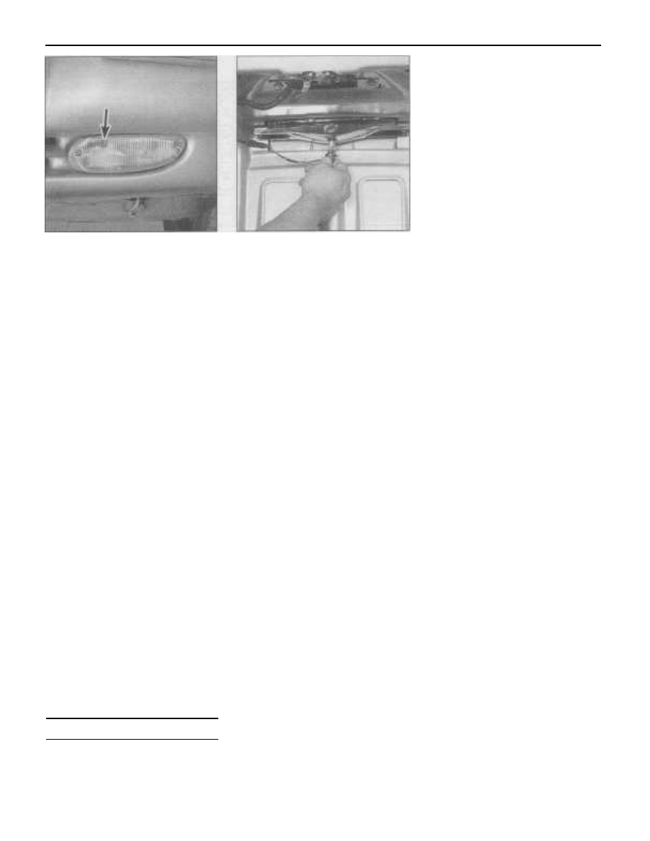
16 Bulb replacement

Ash tray/cup holder bulb

1

Insert a small screwdriver into the slot in

16.6 Removing the center mounted brake

light from the trunk lid. This bulb is a

halogen type. Don't touch it with your

bare hands because the oil from your skin

could cause the bulb to fail prematurely

the light bezel and pry it from the cubby bin.
2

Pull the light socket from the light bezel.

3

Remove the bulb from the socket.

4

Installation is the reverse of removal.

Center mounted brake light

Refer to illustration 16.6
Warning: Halogen bulbs are gas-filled and
under pressure and may shatter if the surface
is scratched or the bulb is dropped. 
Wear eye

protection and handle the bulbs carefully,
grasping only the base whenever 
possible.

Don't touch the surface of the bulb with your
fingers 
because the oil from your skin could
cause it to overheat and fail prematurely. If

you do touch the bulb surface, clean it with

rubbing alcohol.
5

Open the trunk lid.

6

Rotate the bulb holder 1/4-turn counter-

clockwise and withdraw it from the light bezel
(see illustration).
7

Grasp the bulb and pull it out of the

holder.
8

Using gloves or a clean shop towel,

insert the new bulb into the holder. Note: This
bulb is a halogen type. Don't touch the sur-
face of the bulb with your fingers because the
oil from your skin could 
cause it to overheat
and fail prematurely. If you happen to touch
the bulb surface, clean it with rubbing alco-
hol.
9

Insert the holder into the light bezel and

rotate it clockwise to lock it in place. Close
the trunk.

Dome lamp

10

Using a small screwdriver, pry the dome

li ght lens from the light assembly.

11

Remove the bulb from the socket.

12 Installation is the reverse of removal.

Fog light

Warning: Halogen bulbs are gas-filled and
under pressure and may shatter if the surface
is scratched or the bulb is dropped. Wear eye

protection and handle the bulbs carefully,

grasping only the base whenever possible.
Don't touch the surface of the bulb with your
fingers 
because the oil from your skin could
cause it to overheat and fail prematurely. If

you do touch the bulb surface, clean it with

rubbing alcohol.

13

Remove the screws securing the fog

li ght assembly to the front bumper and with-
draw it from the bumper.

14

Grasp the bulb holder and rotate it 1/4-

turn counterclockwise and then remove it
from the light bezel.

15

Grasp the bulb and pull it out of the

holder.

16

Using gloves or a clean shop towel,

insert the new bulb into the holder. Note: This
bulb is a halogen type. Don't touch the sur-
face of the bulb with your fingers because the
oil from your skin could 
cause it to overheat
and fail prematurely. If you happen to touch
the bulb 
surface, clean it with rubbing
alcohol.

17 Insert the holder into the light bezel and

rotate it clockwise to lock it in place.

18 Install the light bezel into the bumper

and secure it with the mounting screws.

19

Check and adjust the fog light beam

(see Section 15).

Glove box light

20

Open the glove box.

21

Pull down on the light/switch assembly

to disengage it from the instrument panel.
22

Pull bulb from socket.

23 Installation is the reverse of removal.

Headlight bulb

Refer to illustration 16.25
Warning: Halogen bulbs are gas-filled and
under pressure and may shatter if the surface
is scratched or the bulb is dropped. Wear eye
protection and handle the bulbs carefully,
grasping only the 
base whenever possible.
Don't touch the surface of the bulb with your
fingers because the oil from your skin could
cause it to overheat and fail prematurely. If
you do touch the bulb 
surface, clean it with
rubbing alcohol.
24

Remove the headlight assembly (see

Section 14).
25

Grasp the headlight bulb holder retain-

ing ring and rotate it 1/4-turn counterclock-
wise and remove the bulb holder from the
headlight assembly (see illustration).
26

Grasp the bulb and pull it out of the

holder.
27

Using gloves or a clean shop towel,

insert the new bulb into the holder. Note:
Don't touch the surface of the bulb with your
fingers 
because the oil from your skin could
cause it to overheat and fail prematurely. If

you happen to touch the bulb surface, clean it

with rubbing alcohol.
28 Install the bulb holder in the headlight
assembly and rotate it clockwise to lock it in
place. Attach the electrical connectors to the
bulb holders.
29 Install the headlight assembly (see Sec-

15.20 Fog light adjusting screw (arrow)

Chapter 12 Chassis electrical system

12-9

16.25 After removing the headlight bulb holder retaining ring
(arrow), the bulb/holder can be withdrawn from the headlight

assembly - (A) indicates the park/turn signal bulb/holder

16.31 Replacing an instrument cluster bulb

16.50 Inside the trunk, remove these

plastic wing-nuts (arrows)

tion 14) and adjust if necessary (see Sec-
tion 15).

Instrument panel bulbs

Refer to illustration 16.31
Note: Depending on the location of the bulb
being replaced, you may be able 
to access
the bulb from under the dashboard.
30

Remove the instrument cluster (see

Section 20).
31

Grasp the bulb holder and rotate it 1/4-

turn counterclockwise and then remove it
from the instrument cluster (see illustration).
32

Pull the bulb from the holder.

33 Install the new bulb into the holder.
34 Insert the holder into the instrument
panel and rotate it clockwise to lock it in
place.
35 Install the instrument cluster (see Sec-
tion 20).

License plate light

36

Remove the license plate light assembly

retaining screws and withdraw it from the
rear bumper.
37

Grasp the bulb holder and rotate it 1/4-

turn counterclockwise and then remove it
from the light bezel.

16.51 Withdraw the tail light assembly

from the quarter panel and disconnect the

electrical connector

40 Insert the holder into the light bezel and

rotate it clockwise to lock it in place.

41

Install the light bezel into the bumper

and secure it with the mounting screws.

Park/turn signal bulb

42

Remove the headlight assembly (see

Section 14).

43

Grasp the bulb holder and rotate it 1/4-

turn counterclockwise and remove the holder
from the headlight assembly (see illustration

16.25).
44

To remove the bulb from the holder,

push it down slightly then rotate it 1/4-turn
counterclockwise and withdraw it from the
holder.
45 Install the new bulb into the holder.
46 Install the bulb holder in the headlight
assembly and attach the electrical connec-

tors to the bulb holders.

47 Install the headlight assembly (see Sec-

tion 14) and adjust if necessary (see Sec-
tion 15).

Tail, stop, back-up and turn

signal bulbs

Refer to illustrations 16.50, 16.51 and 16.52

16.52 Remove the tail/stop light from the

tail light assembly

tail lamp assembly.

50

Unscrew and remove the plastic wing-

nuts securing the tail light assembly to the
quarter panel (see illustration).
51

Withdraw the tail light assembly from

the quarter panel and disconnect the wiring
harness connector from the tail lamp assem-
bly (see illustration).
52

To replace a bulb, rotate the bulb hold-

er 1/4-turn counterclockwise and withdraw it
from the light bezel, then pull the bulb from
the holder (see illustration).
53 Installation is the reverse of removal.

Trunk light

54

Open the trunk.

55

Carefully insert a trim stick (plastic or

wood) between the rear self reinforcement
panel and cargo lamp lens. Carefully pry
downward and remove it.
56

Grasp the bulb and remove it from the

socket.
57 Installation is the reverse of removal.

Underhood lamp

58

Disconnect the wiring harness from the

lamp assembly.
59

Rotate the bulb counterclockwise, then

remove it.
60 Installation is the reverse of removal.

38

Remove the bulb from the holder.

48

Open the trunk.

39

Install the new bulb into the holder.

49

Separate the trunk lining from the rear

12

12-10

Chapter 12 Chassis electrical system

17.4 Disconnecting the electrical connectors and antenna lead

from the rear of the radio

17.3 Radio mounting screws (arrows)

Visor vanity lamp

61

Lower the visor.

62

Carefully insert a trim stick (plastic or

wood) between the visor and vanity lamp

lens. Carefully pry outward and remove it.

63

Grasp the bulb and remove it from the

socket.
64 Installation is the reverse of removal.

17

Radio, amplifier and speakers -

removal and installation

Warning: These models have airbags. Always
disable the airbag system before working in
the vicinity of the impact 
sensor, steering col-
umn or instrument panel to avoid the possibil-
ity of accidental deployment of the 
airbag,
which could cause personal injury (see Sec-
tion 29).

17.7 Amplifier mounting details

Caution: Do not operate the radio without the

speakers attached, damage to the amplifier
may occur.

Radio

Removal

Refer to illustrations 17.3 and 17.4

1

Disconnect the negative battery cable

from the ground stud on the left shock tower

(see Chapter 5, Section 1).

2

Remove the center bezel (see Chap-

ter 11).
3

Remove the mounting screws (see

illustration).

4

Pull the radio out of the instrument

panel. Release the clips and disconnect the

electrical connectors and the antenna lead
from the rear of the radio (see illustration)
and remove it from the vehicle.

Installation

5

Installation is the reverse of removal.

Amplifier

Removal

Refer to illustration 17.7
6

Remove the left front (driver's) seat (see

Chapter 11).
7

Remove the screws and nut securing

the amplifier to the floorpan (see illustra-
tion).
8

Disconnect the electrical connectors

from the amplifier and remove it from the
vehicle.

Installation

9

Installation is the reverse of removal.

Speakers

Door

Removal
Refer to illustration 17.12
10

On vehicles equipped with manual win-

dows, remove the window crank using a spe-
cial tool (available at most auto parts stores)
or by working a cloth back-and-forth behind
the handle to dislodge the retaining clip (see

Chapter 11).

11

Carefully, pry the speaker grille from the

door trim panel.
12

Remove the speaker mounting screws

and withdraw the speaker from the door trim
panel (see illustration).
13

Disconnect the electrical connector and

remove the speaker from the vehicle.

Installation
14 Installation is the reverse of removal.

Instrument panel

Removal
15

Remove the instrument panel top cover

(see Chapter 11).
16

Remove the mounting screws, lift the

speaker out of the instrument panel, then dis-
connect the electrical connector and remove
the speaker from the vehicle.

Installation
17 Installation is the reverse of removal.

Rear

Removal
Refer to illustration 17.24
18

Remove the rear lower seat cushion (see

Chapter 11).

17.12 Front door speaker mounting

screws (arrows)

Chapter

12

Chassis electrical

system

12-11

17.24 Parcel shelf and rear

speaker mounting details

18.1 Use a small end-wrench to remove

the antenna mast (fixed antenna)

RUBBER

GROUND

GROMMET

STRAP

18.3 Disconnect the lead from the

antenna body

19

Remove the rear seat back (see Chap-

ter 11).
20

Remove the bolts securing the rear seat

belt anchors to the floorpan.

21

Disengage the clips holding the left and

right upper quarter trim pieces to the inner
quarter panels.
22

Route the seat belt webbing through the

access hole in each upper quarter trim piece
and remove them from the vehicle.
23

Using a screwdriver, pry off the left and

right quarter panel trim extensions (see
Chapter 11).
24

Remove the push-in fasteners securing

the parcel shelf to the trunk closure panel
(see illustration).
25

Pull the parcel shelf forward to disen-

gage the clip securing parcel shelf to the
trunk closure panel and remove it from the
vehicle.
26

Remove the mounting screws, lift the

speaker(s) out of the trunk closure, discon-
nect the electrical connector(s) and remove it
from the vehicle.

Installation
27 Installation is the reverse of removal,
making sure that the speaker wire connectors
face outward (toward the rear wheels).

18.4 Remove the antenna mounting bolt

Warning: These models have airbags. Always
disable the 
airbag system before working in
the vicinity of the impact sensor, steering col-
umn or instrument panel to avoid the possibil-
ity of accidental deployment of the airbag,
which could 
cause personal injury (see Sec-
tion 29).

Fixed antenna

Removal

Refer to illustrations 18.1, 18.3 and 18.4

1

Use a small open end wrench and

unscrew the antenna mast from the antenna
body (see illustration).
2

Working inside the trunk, detach the

li ner from the right side of the trunk.
3

Disconnect the antenna lead from the

base of the antenna body (see illustration).
4

Remove the mounting bolt securing the

antenna body to the rear quarter panel (see
illustration).
5

Withdraw the antenna body from the

rear quarter panel.

Installation

6

Installation is the reverse of removal.

18.9 Power antenna mounting details

Power antenna

Removal

Refer to illustration 18.9

7

Disconnect the negative battery cable

from the ground stud on the left shock tower
(see Chapter 5, Section 1).
8

Working inside the trunk, detach the

li ner from the right side of the trunk.

9

Detach the drain tube from the antenna

(see illustration).

10

Disconnect the antenna lead from the

power antenna harness.
11

Disconnect the electrical connector

from the antenna motor.

12

Remove the bolts securing the ground

strap and antenna brace to the rear quarter
panel.

13

Withdraw the antenna from the rear

quarter panel.

18 Antenna - removal and

installation

12

12-12

Chapter 12 Chassis electrical system

18.15 Remove the power antenna cap nut

TACHOMETER ...6000 rpm
SPEEDOMETER ...100mph (220 kmh)

FUEL GAUGE pointer ON ...F

TEMPERATURE GAUGE pointer ON ...H

TACHOMETER ...3000 rpm
SPEEDOMETER ...75mph (120 kmh)
FUEL GAUGE pointer ON ...1/2
TEMPERATURE GAUGE pointer ON ...midscale

TACHOMETER ...3000 rpm
SPEEDOMETER ...55mph (100 kmh)
FUEL GAUGE pointer ON ...1/2
TEMPERATURE GAUGE pointer ON ...midscale
TACHOMETER ...1000 rpm
SPEEDOMETER ...20mph (40 kmh)
FUEL GAUGE pointer ON ...E

TEMPERATURE GAUGE pointer ON ...0

1,.5a Instrument cluster CHEC 1 chart

19.5b Instrument cluster CHEC 2 chart

ANTENNA MAST

TOOTH (SERRATED)

SIDE MUST FACE TO

FRONT OF CAR

GROMMET

FRON T

18.17 Power antenna mast, contact spring and'drive rod

assembly details

CHECK ENGINE
SEAT BELT
AIRBAG
CHARGING SYSTEM

LOW FUEL
HIGH BEAM INDICATOR
ENGINE TEMPERATURE

CRUISE

Installation

14 Installation is the reverse of removal.
Make sure that the fender grommet locating
tab is in line with the slot in the body before
installing the antenna. Make sure the ball of
the antenna body is fully seated in the grom-
met.

Power antenna mast

Removal

Refer to illustrations 18.15 and 18.17
15

Remove the cap nut (see illustration).

16

Turn the ignition key to the ACCES-

SORY position.
17

Turn the radio ON and while the antenna

is moving UP, grab the mast and pull it out of

the antenna body. The antenna mast, contact

spring and drive rod should all come out at

this time (see illustration).

Installation

18 Insert the new antenna mast, contact
spring and drive rod into the body with the
drive rod teeth facing toward the antenna
motor (remove the trunk lining if necessary).
19

Turn the radio OFF and guide the drive

rod into the body.

20 Install the cap nut. Note: The antenna
may not completely retract 
after initial instal-
lation. Turn the radio ON-and-OFF to cycle

the antenna up-and-down. The mast should
completely retract after raising and lowering
the antenna a few times.

19 Instrument cluster self-diagnosis

General description

1

The instrument cluster is equipped with

a self-diagnosis feature. When activated, the
electronic display, odometer/transmission
range indicator and all indicator lamps will
ill uminate in a specific sequence.
2

If the instrument cluster is not receiving

power from the CCD bus, the cluster will
appear non-functional except the airbag indi-
cator lamp will illuminate and a NO BUS mes-
sage will be displayed. If this message is dis-
played, further diagnosis should be per-

formed by a dealer service department or

other qualified repair shop.

Starting the self-diagnosis

Refer to illustrations 19.5a, 19.5b, 19.5c,

19.5d, 19.5e and 19.5f
3

While depressing the odometer/trip

reset button, turn the ignition key to the

OFF/RUN/START position.
4

This will initiate an electronic display

system check and the illumination (in

sequence) of all CCD bus activated instru-
ment cluster warning indicators. Due to the
complexity of replacing the instrument cluster
circuit board, gauges and transmission range
indicator, the home mechanic should limit
service to bulb replacement (see Section 16).
If the instrument cluster circuit board, gauge
or transmission range indicator replacement
is indicated, take the vehicle to a dealer ser-
vice department or other qualified repair shop
for service.
5

There are four check (CHEC) functions

(see illustrations):

a) CHEC 1 - Gauges: If all gauges fail to

move or do not indicate at the proper
locations, the instrument cluster circuit
board is faulty and should be replaced. If
any one gauge fails to move or indicate

properly, have it replaced.

b) CHEC 2 - Warning lamps: If any lamp

listed in Step 1 does not illuminate,
check the bulb operation. If the bulb is
OK, the instrument cluster circuit board

is faulty and should be replaced.

c) CHEC 3 - Odometer/trip meter: If any

LED does not illuminate, have it

replaced.

d) CHEC 4 - Transmission range indica-

tor/Autostick indicator: If any LED does

not illuminate, have it replaced.

Chapter 12 Chassis electrical system

12-13

PRND3L
PRND3L AND BOX AROUND P
PRND3L AND BOX AROUND R
PRND3L AND BOX AROUND N
PRND3L AND BOX AROUND D
PRND3L AND BOX AROUND 3
PRND3L AND BOX AROUND L
PRND3L AND ALL BOXES
END

19.5d Instrument cluster CHEC 4 chart - automatic transaxle

models without the Autostick option

TRIP
ODOMETER CENTER
ODOMETER LOWER RIGHT
ODOMETER BOTTOM
ODOMETER LOWER LEFT
ODOMETER UPPER LEFT
ODOMETER TOP
ODOMETER UPPER RIGHT
ALL ODOMETER V/F DISPLAY DIGIT SEGMENTS

ON

19.5c Instrument cluster CHEC 3 chart

CHEC 4 - TRANSMISSION RANGE INDICATOR

LED DISPLAY

AUTOSTICK

PRND AS 1 AND AS BOX
PRND AS 2 AND AS BOX

PRND AS 3 AND AS BOX
PRND AS 4 AND AS BOX
PRND AS AND BOX AROUND P
PRND AS AND BOX AROUND R
PRND AS AND BOX AROUND N
PRND AS AND BOX AROUND D
PRND AS 1234 AND ALL BOXES
END

19.5e Instrument cluster CHEC 4 chart - 1997 and earlier

automatic transaxle models with the Autostick option

19.5f Instrument cluster CHEC 4 chart - 1998 and later automatic

transaxle models with the Autostick option

CHEC 4 - TRANSMISSION RANGE INDICATOR

LED DISPLAY

AUTOSTICK

PRND1234 AND BOX AROUND 1
PRND1234 AND BOX AROUND 2
PRND1234 AND BOX AROUND 3
PRND1234 AND BOX AROUND 4
PRND1234 AND BOX AROUND P
PRND1234 AND BOX AROUND R
PRND1234 AND BOX AROUND N
PRND1234 AND BOX AROUND D
PRND1234 AND ALL BOXES
END

20 Instrument cluster - removal and

installation

Warning: These models have airbags. Always
disable the airbag system before working in
the vicinity of the impact 
sensor, steering col-
umn or instrument panel to avoid the possibil-
ity of accidental deployment of the airbag,
which could 
cause personal injury (see Sec-
tion 29).

Removal

Refer to illustration 20.3

1

Disconnect the negative battery cable

from the ground stud on the left shock tower
(see Chapter 5, Section 1).

2

Remove instrument cluster hood (see

Chapter 11).

3

Remove the 4 screws securing the clus-

ter to the instrument panel (see illustration).
4

Slightly withdraw the instrument cluster

from the instrument panel, disconnect the
electrical wiring harness connectors and

remove the cluster from the vehicle.

Installation

5

Installation is the reverse of removal.

21

Horn - check, removal and
installation

Warning: These models have airbags. Always

disable the airbag system before working in
the vicinity of the impact 
sensor, steering col-
umn or instrument panel to avoid the possibil-

ity of accidental deployment of the airbag,

which could cause personal injury (see Sec-

tion 29).

Check

Refer to illustrations 21.2, 21.3 and 21.9

1

If the horn doesn't sound, check the

horn fuses in the Power Distribution Center
(PDC) and fuse block (see Section 3). If a fuse
is blown, replace it and retest. If it blows
again, there is a short circuit in the horn or

wiring between the horn and fuse block.
2

Check the circuit to the horn relay;

remove the cover from the interior fuse block.

21.2 Horn relay (A) and rear window defogger relay (B)

12

12-14

Chapter

12

Chassis electrical

system

21.9 Lower horn electrical connector

21.3 Interior fuse block relay terminal identification

CIRCUIT

BREAKERS

Depress the horn pad on the steering wheel,
a "click" should be heard as the horn relay
activates. If the relay "clicks" proceed to
Step 7. If the horn relay cannot be heard,
remove it from the interior fuse block (see
illustration).
3

Using a fused jumper wire, connect ter-

minals 8 and 10 in the fuse block (see illus-
tration). 
The horns should sound.
4

Using a voltmeter, check for battery

voltage to terminals 6 and 8 in the fuse block.
Battery voltage should be present. If voltage
is not present, repair the circuit as required
(see Section 31).
5

Connect a voltmeter between terminals

6 and 7 in the fuse block. No voltage should
be present. While observing the voltmeter,
press the horn pad on the steering wheel -
battery voltage should be present when the
horn pad is depressed and absent when
released. If the voltage is not present with the
horn pad depressed, the problem exists in
the steering column wiring. If voltage is pre-
sent, replace the relay.
6

Reinstall the relay into the fuse block.

7

Check for battery voltage at the horn;

raise the front of the vehicle and support it
securely on jackstands.
8

Remove the push-in fasteners and

remove lower splash shield to access the
horn(s) electrical connectors.
9

Disconnect the electrical connector

from the discrepant horn (see illustration).
Connect a voltmeter to the wiring harness
connector and depress the horn pad on the
steering wheel. Battery voltage should be

present when the horn pad is depressed. If
no voltage is present, there is a fault in the

wiring. If voltage is present, replace the horn.

10 if no voltage is present, connect the

voltmeter positive probe to the DARK

GREEN/PINK wire and the other probe to a

good ground on the chassis. Depress the

horn pad. If battery voltage is now present,

the short exists in the ground circuit. Repair
the circuit as required (see Section 31). If
voltage is not present, the short exists in the

power circuit. Remove the horn relay from the

fuse block and using a fused jumper wire,

connect terminals 8 and 10. Battery voltage

should be present at the horn connector. If it
is, replace the relay. If no voltage is present,
repair the circuit as required (see Section 31).
11

After testing is complete, reattach the

horn electrical connector, install the splash
shield and lower the vehicle.

Removal

Refer to illustration 21.12
12

Both horns are located behind the front

bumper on the right side frame rail, one
above the other (see illustration).
13

Raise the front of the vehicle and sup-

port it securely on jackstands.
14

Remove the push-in fasteners and

remove lower splash shield.
15

Disconnect the horn electrical connec-

tor, remove the mounting bolt and withdraw
the horn from the vehicle.

Installation

16 Installation is the reverse of removal.

Check horn operation after installation.

Warning: These models have airbags. Always
disable the airbag system before working in
the vicinity of the impact 
sensor, steering col-
umn or instrument panel to avoid the possibil-
ity of accidental deployment of the airbag,
which could 
cause personal injury (see Sec-
tion 29).

Check

1

With the ignition switch ON (engine

OFF), depress the defogger switch. The indi-

cator lamp should illuminate and remain on

for approximately 10 minutes then go out. If
the indicator illuminates, the relay is opera-
tional - check the rear window defogger heat

grid (see Section 23). If the indicator lamp

fails to illuminate, either the LED light in the

switch is faulty, a short exists in the circuit or

the rear window defogger relay is faulty.

Note: The indicator will illuminate for 10 min-

utes the first time the switch is activated and

21.12 The horns (arrows) are located

behind the front bumper on the right side

frame rail, one above the other

then will only remain on for 5 minutes each
time the switch is depressed thereafter,
unless the ignition switch is turned to the OFF
position which resets the timer located inside
the Body Control Module.
2

If the indicator light fails to illuminate,

check the circuit to the rear window defogger

relay; remove the cover from the interior fuse
block. Depress the defogger switch, a "click"

should be heard as the rear window defogger

relay activates (see illustration 21.2). If the
relay "clicks" check the rear window defog-
ger heat grid (see Section 23). If the rear win-
dow defogger relay cannot be heard, remove
it from the fuse block and with the ignition
key ON (engine OFF), check for battery volt-
age to the rear window defogger relay termi-
nals 15 and 11 (see illustration 21.3). Battery
voltage should be present. If no voltage is
present, repair the circuit (see Section 31).
3

Next, connect the voltmeter between

relay terminals 13 and 15. With the defogger
switch depressed, battery voltage should be
present. If battery voltage is present, replace
the relay. If no voltage is present, repair the
circuit.
4

Remove the heater/air conditioning con-

trol assembly (see Chapter 3), but DO NOT
disconnect the electrical connectors.

22 Rear window defogger switch -

check and replacement

Chapter 12 Chassis electrical system

12-15

23.4 Rear window defogger testing locations

BREAK

GRID LINE

MASKING TAPE

23.13 When repairing a heat element, place masking tape on both

sides of the element to make a straight path for the epoxy

5

With the ignition switch OFF, use an

ohmmeter to backprobe the 8-way electrical
connector RED wire (+) and the BLACK/PINK
(-) wire. Note: To backprobe an electrical
connector, use pins or paper clips inserted
into the rear of the connector (or wire) to facil-
itate meter attachment. Be careful not to
short the probes during this process.
6

Depress the defogger switch, the resis-

tance should be between 500 and 520 ohms.
If the resistance is out of tolerance, replace
the defogger switch.
7

Next, switch the multi-meter to the volts

scale and turn the ignition key ON (engine
OFF). Battery voltage should be present. If
not, repair the circuit (see Section 31).

Replacement

8

The rear window defogger switch is

incorporated into the heating/air conditioning
control assembly, refer to Chapter 3 for
replacement procedures.

23 Rear window defogger heat grid

- check and repair

6

Next, connect the voltmeter negative

probe to a good ground on the chassis. If the
ground circuit is OK, the reading should stay

the same. If not, repair the ground circuit (see

Section 31).
7

Connect the negative lead to terminal B,

then touch each grid line at the mid-point
with the positive lead.

8

The reading should be approximately 5

to 6 volts. If the reading is 0, there is a break

between mid-point C and terminal A.

9

A 10 to 12 volt reading is an indication of

a break between terminal B and mid-point C.

Move the lead toward the break; the voltage

will change when the break is crossed.

Repair

Refer to illustration 23.13

10

Repair the break in the heating element

using repair kit recommended specifically for

this purpose, such as Mopar Repair Kit No.
4267922 (or equivalent). Included in this kit is

plastic conductive epoxy.
11

Prior to repairing a break, turn off the

system and allow it to de-energize for a few
minutes.

12

Lightly buff the element area with fine

steel wool, then clean it thoroughly with rub-
bing alcohol.
13

Use masking tape to mask off the area

of repair (see illustration).
14

Mix the epoxy thoroughly, according to

the instructions on the package. Warning:
Read the warning instructions included with
the kit relating to the chemical component
makeup of the kit (epoxy resin and amine type
hardener) and protect yourself accordingly.
15

Follow the instructions in the kit and

apply the conductive epoxy material to the
slit in the masking tape, overlapping the
undamaged area about 3/4-inch on either
end.
16

Allow the repair to cure for 24 hours (at

room temperature) before removing the tape
and using the system.

24 Cruise control system -

description and check

General description

Refer to illustration 24.1

1

The cruise control system maintains

1

The rear window defogger consists of a

number of horizontal elements baked onto
the inner surface of the rear window glass.
2

Small breaks in the element can be

repaired without removing the rear window.

Check

Refer to illustration 23.4
Note: When measuring the voltage at the rear
window defogger 
heat grid, wrap a piece of
aluminum foil around the voltmeter probes
and press the foil against the heating element
with your finger.
3

Turn the ignition switch and defogger

system switches to the ON position.
4

Working within the back seat area,

ground the negative lead of

a

voltmeter to

terminal B (lower corner passengers side)
and the positive lead to terminal A (lower cor-
ner drivers side) of the defogger grid (see
illustration).
5

The voltmeter should read between 10

and 12 volts. If the reading is lower, there is a
poor ground connection. Check the ground
connection at the right rear wheel well.

24.1 Cruise control system - mechanical components

12


Content   ..  33  34  35  36   ..