содержание .. 47 48 49 50 ..
Peugeot 405. Manual - part 49
22 Power steering pump -
removal and refitting
3
XU5 and XU9 (except XU9J4)
engine models
Removal
1 Disconnect the battery negative lead.
2 Drain the fluid from the hydraulic system as
follows.
a) Remove the cap from the fluid reservoir.
b) Place a container under the high pressure
fluid pipe union on the steering gear, then
unscrew the union.
c) Allow the fluid to drain into the container.
d) Turn the steering from lock-to-lock
several times to completely drain the
system.
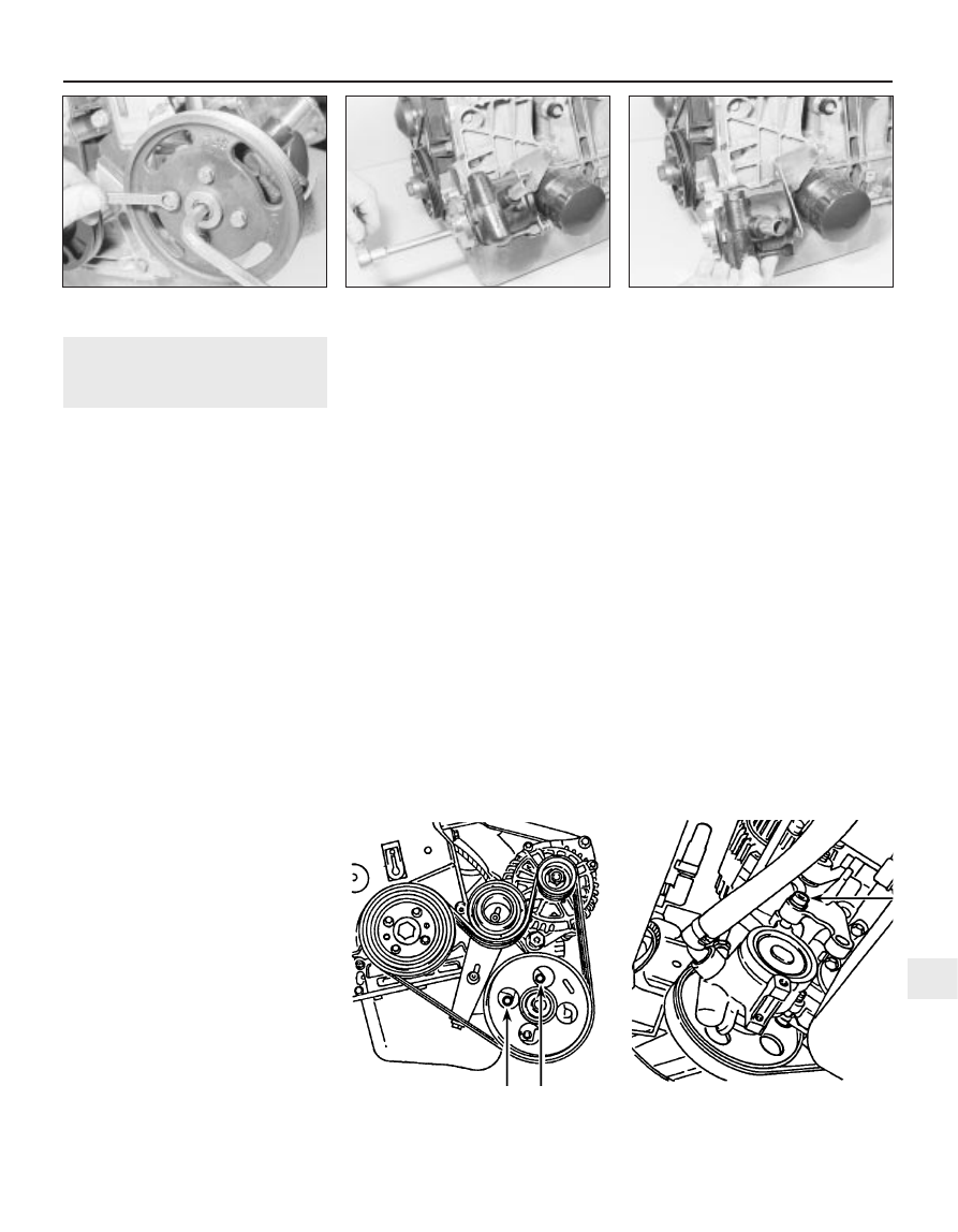
3 Counterhold the pump spindle, and slacken
the pump pulley securing bolts (see
illustration).
4 Remove the pump drivebelt as described in
Chapter 1.
5 Remove the bolt securing the alternator to
the adjuster bracket, then swing the alternator
upwards, clear of the power steering pump.
6 Remove the securing bolts, and withdraw
the pump pulley.
7 Unscrew the fluid pipe union, and
disconnect the pipe from the pump.
8 Slacken the hose clip, and disconnect the
fluid hose from the pump. If the hose clip is of
the crimped type, discard it and fit a new
worm-drive clip on refitting.
9 Unscrew the two front and two rear
securing bolts, and withdraw the pump from
the mounting brackets (see illustrations).
10 The pump cannot be overhauled, and if
faulty must be renewed.
Refitting
11 Refitting is a reversal of removal, bearing
in mind the following points.
a) Tighten all fixings to the specified torque.
b) Where applicable, use a new securing clip
when reconnecting the fluid hose to the
pump.
c) Refit and tension the drivebelt as
described in Chapter 1.
d) On completion, refill and bleed the
hydraulic system as described in
Section 21.
XU9J4 engine models
Removal
12 Proceed as described in paragraphs 1
and 2.
13 Remove the pump drivebelt (Chapter 1).
14 Unscrew the fluid pipe union, and
disconnect the pipe from the pump.
15 Slacken the hose clip, and disconnect the
fluid hose from the pump. If the hose clip is of
the crimped type, discard it and fit a new
worm-drive clip on refitting.
16 Unscrew the pump mounting bolts, and
withdraw the pump from the mounting
brackets. Recover any washers and spacers
from the bolts, noting their locations to ensure
correct refitting.
17 The pump cannot be overhauled, and if
faulty must be renewed.
Refitting
18 Refer to paragraph 11.
XU7 and XU10 engine models
without air conditioning
Removal
19 Proceed as described in paragraphs 1
and 2.
20 Apply the handbrake, then jack up the
front of the vehicle and support securely on
axle stands (see “Jacking and Vehicle
Support”). Remove the front right-hand
roadwheel.
21 Remove the right-hand wheel arch liner,
with reference to Chapter 11 if necessary.
22 Remove the pump drivebelt (Chapter 1).
23 Unscrew the fluid pipe union, and
disconnect the pipe from the pump.
24 Slacken the hose clip, and disconnect the
fluid hose from the pump. If the hose clip is of
the crimped type, discard it and fit a new
worm-drive clip on refitting.
25 Unscrew the two front pump mounting
bolts, which can be accessed through the
holes in the pump pulley (see illustration).
26 Unscrew the rear pump mounting bolt,
and withdraw the pump from the engine (see
illustration).
Refitting
27 Refer to paragraph 11.
XU7 and XU10 engine models
with air conditioning
Removal
28 Proceed as described in paragraphs 1
and 2.
29 Unscrew the fluid pipe union, and
disconnect the pipe from the pump.
Suspension and steering 10•15
22.9b . . . and remove the pump - XU5 and
XU9 engines (engine removed for clarity)
22.26 Pump rear mounting bolt (arrowed) -
XU7 and XU10 engines
without air conditioning
22.25 Unscrew the two front pump
mounting bolts (arrowed) - XU7 and
XU10 engines without air conditioning
22.9a Unscrew the securing bolts . . .
22.3 Counterhold the pump spindle and
slacken the pulley bolts
10