содержание .. 46 47 48 49 ..
Peugeot 405. Manual - part 48
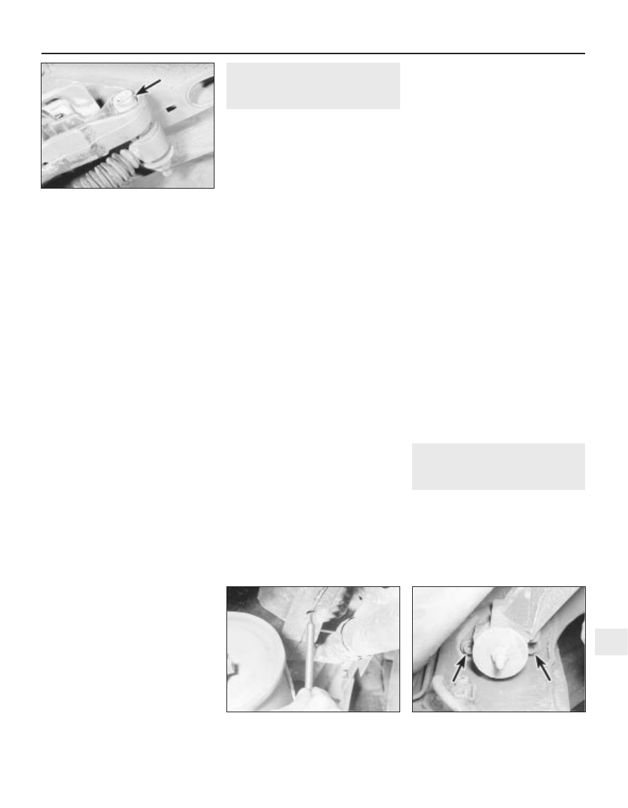
shock absorber upper and lower securing
nuts. Recover the washers (see illustration).
4 Tap the bolts from the mountings to free the
shock absorber, then withdraw the unit from
under the vehicle.
Testing
5 Examine the shock absorber for signs of
fluid leakage or damage. Test the operation of
the shock absorber, while holding it in an
upright position, by moving the piston through
a full stroke and then through short strokes of
50 to 100 mm. In both cases, the resistance
felt should be smooth and continuous. If the
resistance is jerky, or uneven, or if there is any
visible sign of wear or damage, renewal is
necessary.
6 Also check the rubber mounting bushes for
damage and deterioration. New bushes can
be fitted using a long bolt, nut and spacers to
draw the bush into position. Lubricate the new
bush with soapy water to aid fitting.
7 Inspect the shanks of the mounting bolts
for signs of wear or damage, and renew as
necessary.
Refitting
8 Prior to refitting the shock absorber, mount
it upright in the vice, and operate it fully
through several strokes in order to prime it.
Apply a smear of multi-purpose grease to
both the shock absorber mounting bolts.
9 Manoeuvre the shock absorber into
position, and insert its mounting bolts (with
washers in place). Note that the bolts fit from
the inside of the vehicle, ie the nuts fit on the
roadwheel side of the shock absorber.
10 Fit the washers and new nuts to the
mounting bolts, but do not tighten the fixings
at this stage.
11 Measure the distance between the shock
absorber bolt centres, and load the vehicle (by
adding weight to the luggage compartment)
until a distance of 328.0 mm is obtained
between the bolt centres. Tighten the shock
absorber mounting nuts and bolts to the
specified torque.
12 Drive the vehicle off the ramps.
14 Rear axle assembly -
removal and refitting
4
Removal
Note: Before carrying out this procedure, it is
advisable to run the fuel tank as near empty as
possible to minimise the amount of fuel which
has to be drained from the tank.
1 Chock the front wheels, then jack up the
rear of the vehicle and support securely on
axle stands, until the trailing arms are at
maximum extension, with the roadwheels still
resting on the ground (see “Jacking and
Vehicle Support”).
2 Where applicable, remove the rear
underbody shield.
3 Remove the rear and intermediate exhaust
sections as described in Chapter 4.
4 Empty the fuel tank by either disconnecting
the filler pipe and draining, or by siphoning the
fuel out through the filler neck. In either case,
collect the fuel in a container which can be
sealed.
5 Disconnect the fuel filler pipe from the tank
(If not already done). Plug the open ends of
the tank and the hose to prevent dirt ingress.
6 Remove the rear exhaust heat shield from
the underbody.
7 Disconnect the handbrake cables from the
adjuster mechanism under the rear
underbody, with reference to Chapter 9.
8 Release the handbrake cables from any
clips and brackets, and move them clear of
the suspension components to facilitate
removal.
9 Loosen the fuel tank support strap bolts as
far as possible without removing them, and
lower the fuel tank.
10 Disconnect the brake fluid pipes at the
unions on the rear suspension assembly, with
reference to Chapter 9. Plug the open ends of
the unions.
11 On models with a load-sensitive rear
brake pressure regulating valve, disconnect
the hydraulic pipes at the valve. Again, plug
the opens ends of the pipes and the valve.
12 Where applicable, remove the rear ABS
wheel sensors. Note that there is no need to
disconnect the wiring connectors, but unclip
the wiring harnesses from the rear suspension
components, and move the sensors to one
side, clear of the working area.
13 Place a trolley jack under the rear
suspension tubular crossmember to support
the suspension assembly.
14 Make a final check to ensure that all
relevant pipes and wires have been
disconnected to facilitate removal of the
suspension assembly.
15 Using a long-reach splined adapter,
unscrew the suspension assembly rear
securing bolts, accessible through the holes
in the suspension assembly side members
(see illustration).
16 Working at the front of the suspension
assembly, unscrew the two bolts on each side
securing the front mountings to the
underbody
(see illustration).
17 Lower the trolley jack slightly, and pull the
suspension rearwards. If necessary, raise the
vehicle body in order for the suspension to
clear the fuel tank, then withdraw the
suspension assembly from under the vehicle.
Refitting
18 Refitting is a reversal of the removal
procedure, bearing in mind the following
points.
a) Tighten all fixings to the specified torque.
b) Bleed the brake hydraulic system as
described in Chapter 9.
c) Adjust the handbrake mechanism as
described in Chapter 9.
d) On completion, have the rear ride height
checked by a Peugeot dealer.
15 Vehicle ride height - checking
5
Checking of the vehicle ride height requires
the use of Peugeot special tools to accurately
compress the suspension in a suspension
checking bay.
The operation should be entrusted to a
Peugeot dealer, as it not possible to carry out
checking accurately without the use of the
appropriate tools.
Suspension and steering 10•11
14.16 Unscrew the two bolts (arrowed) on
each side securing the suspension
mountings to the body
14.15 Using a long-reach splined adapter
to unscrew a suspension assembly
rear securing bolt
13.3 Rear shock absorber
upper mounting bolt (arrowed)
10