Peugeot 405. Manual - part 16


  Главная      Peugeot     Peugeot 405 (1988-1997) - Service And Repair Manual Haynes


поиск по сайту            


содержание   ..  14  15  16  17   ..


Peugeot 405. Manual - part 16


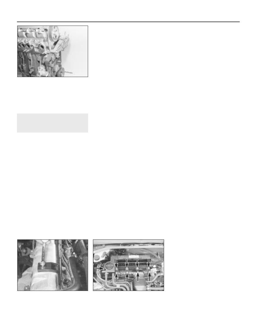
sprocket and locate it in the cylinder head
(see illustration).
14 The crankshaft and camshaft are now
locked in position, preventing rotation.

4

Cylinder head cover -
removal and refitting

2

Removal

Disconnect the battery negative lead.

1580 cc and 1905 cc (8-valve) models

On 1580 cc models, remove the air cleaner-
to-throttle body duct, and the air cleaner
housing, as described in Chapter 4.
On 1905 cc models, remove the air cleaner
housing as described in Chapter 4, and
position the inlet duct clear of the cylinder
head cover.
On all models, slacken the retaining clip
and disconnect the breather hose from the
top of the cylinder head cover. Where the
original crimped-type hose clip is still fitted,
cut it off and discard it. Replace it with a
standard worm-drive hose clip on refitting.
Undo the two nuts/bolts securing the HT
lead retaining bracket to the cylinder head,
and position the bracket clear of the head
cover (see illustration).
Slacken and remove the two remaining
cylinder head cover retaining bolts, along with
their sealing washers.

Lift off the cylinder head cover, and remove
it along with its rubber seal. Examine the seal
for signs of damage and deterioration, and if
necessary, renew it. Also examine the
retaining bolt sealing washers for signs of
damage, and renew if required.

1761 cc and 1998 cc (8-valve) models

Slacken the retaining clips, and disconnect
the breather hoses from the front right-hand
end of the cover. Where the original crimped-
type hose clips are still fitted, cut them off and
discard them; use standard worm-drive hose
clips on refitting.
Slacken the retaining clip, and disconnect
the air cleaner-to-throttle housing duct from
the front of the cylinder head cover. Also
remove the inlet duct from the left-hand side
of the head cover.
10 Release the two retaining clips, then undo
the two retaining screws located at the front,
and remove the air cleaner element cover
from the cylinder head cover. Remove the air
cleaner element, and store it with the cover.
11 Slacken and remove the ten cylinder head
cover retaining nuts, lift off the cylinder head
cover, and remove it along with its rubber seal
(see illustration). Examine the seal for signs
of damage and deterioration, and if
necessary, renew it.

16-valve models

12 Refer to the information given in 
Chapter 4 on depressurising the fuel system.
Slacken the retaining clips, and disconnect
the fuel feed and return hoses from their
unions at the front of the head cover. Where
the original crimped-type hose clips are still
fitted, cut them off and discard them; use
standard worm-drive hose clips on refitting.
Plug both the hose and fuel rail ends, to
prevent the possible entry of dirt into the fuel
system. Mop up any spilt fuel.
13 Undo the retaining nut and bolt securing
the fuel hose retaining clips to the top of the
cylinder head cover, and remove both clips.
Position both fuel hoses clear of the head
cover, so that they do not hinder the removal
procedure.
14 Slacken and remove the remaining seven
retaining bolts, and lift the spark plug access
cover off the cylinder head cover.

15 Pull each ignition HT coil off its spark
plug. Trace the coil wiring back to its
connector on the left-hand end of the cylinder
head. Rotate the locking ring anti-clockwise,
disconnect it from the main wiring loom, and
remove the wiring and coils as an assembly.
16 Disconnect the breather hose from the
left-hand end of the cylinder head. Any
original crimped-type hose clips can be
discarded, as already mentioned.
17 Slacken and remove the twelve cylinder
head cover retaining bolts, noting the correct
fitted positions of any brackets or clips. Note
that the bolts are of four different lengths, and
it is important that each is refitted in the
correct position. To avoid confusion on
refitting, remove each bolt in turn, and store it
in its correct fitted position by pushing it
through a clearly-marked cardboard template.
18 Lift off the cylinder head cover, and
remove it along with its rubber seal. Recover
the four spark plug hole sealing rings from the
cylinder head. Examine all seals for damage
and deterioration, and renew as necessary.

Refitting

1580 cc and 1905 cc models

19 Carefully clean the cylinder head and
cover mating surfaces, and remove all traces
of oil.
20 Fit the rubber seal over the edge of the
cylinder head cover, ensuring that it is
correctly located along its entire length.
21 Carefully refit the cylinder head cover to
the engine, taking great care not to displace
the rubber seal.
22 Check that the seal is correctly located,
then refit the cover retaining bolts and sealing
washers (not forgetting to position the HT lead
bracket under the centre bolt head), and
tighten them to the specified torque.
23 Refit the remaining HT lead bracket
retaining bolt, and tighten it securely.
24 Reconnect the breather hose to the
cylinder head cover, and securely tighten its
retaining clip.
25 Refit the air cleaner housing and duct as
described in Chapter 4, and reconnect the
battery negative terminal.

1761 cc and 1998 cc 8-valve models

26 Clean the cylinder head and cover mating
surfaces, and remove all traces of oil.
27 Locate the rubber seal in the cover
groove, ensuring that it is correctly located
along its entire length.
28 Carefully refit the cylinder head cover to
the engine, taking great care not to displace
the rubber seal.
29 Check that the seal is correctly located,
then refit the cover retaining nuts, and tighten
them evenly and progressively to the
specified torque in the order shown (see
illustration)
.
30 Refit the air cleaner element, and install
the element cover. Securely tighten the cover
retaining screws, and secure it in position with
the retaining clips.

2B•6 XU engine in-car repair procedures

3.13  Camshaft sprocket and crankshaft

pulley locking pins in position 

(1580 cc model shown)

4.11  Cylinder head cover retaining nuts

(arrowed) - 1761 cc and 

1998 cc (8-valve) models

4.5  On 1580 cc and 1905 cc models, undo

the retaining bolts/nuts and move the HT

lead retaining clips clear of the head cover

31 Reconnect the breather hoses, inlet duct
and throttle housing duct to the cover,
tightening their retaining clips securely.
Reconnect the battery.

16-valve models

32 Carry out the operations described in
paragraphs 26 to 28. Fit the four spark plug
hole seals to the recesses in the cylinder head
(see illustration).
33 Check that the seal is correctly located,
then refit the cover retaining bolts. Ensure that
each bolt is refitted in its correct location, and
that all retaining clips/brackets are correctly
positioned. Tighten the cylinder head cover
retaining bolts evenly and progressively to the
specified torque.
34 Reconnect the breather hose to the end of
the cover, and securely tighten its clip.
35 Connect the HT coil wiring loom to its
wiring connector, and secure it in position by
rotating the locking ring. Ensuring that the
wiring is correctly routed, reconnect the HT
coils to the tops of the spark plugs.
36 Refit the spark plug access cover to the
head cover, and refit its retaining bolts (not
forgetting the fuel hose retaining clip). Ensure
that the HT coil wiring is correctly located in
the cover cutout, and that the fuel hoses are
positioned under the retaining clip, then
securely tighten the retaining bolts.

37 Fit the rear fuel hose retaining clip, and
securely tighten its retaining nut.
38 Reconnect the feed and return hoses to
their respective fuel rail unions, ensuring that
their retaining clips are securely tightened.
39 Reconnect the battery negative terminal.
On completion, start the engine and check the
fuel hose unions for signs of leakage.
40 Note:  From early 1992 a modified
camshaft cover gasket has been fitted in
production to 1905 cc models. 
The later type
of gasket can be identified from its grey colour
(the earlier type of gasket was coloured
black). The later type gasket can be fitted to
earlier engines, but the following procedure
must be followed when fitting the later type
gasket to any engine.

a) Apply silicon sealant to the corners of

Nos 1 and 5 camshaft bearing caps, then
after refitting the cover tighten the
securing bolts to the Stage 1 torque
wrench setting in the order shown (see
illustrations)
.

b) Start the engine, and run it at idle speed

for 10 minutes with the bonnet closed.

c) Open the bonnet and check for leaks. If

evident, do not tighten the bolts further,
but remove the cover to establish the
cause, then repeat the fitting operations.

d) Allow the engine to cool for 4 hours, then

tighten the ten outer cover bolts to the
Stage 2 torque wrench setting in the
order shown (see illustration).  This
procedure allows for the settling of the
gasket, which takes place due to the heat
produced by the engine.

5

Crankshaft pulley -
removal and refitting

3

Removal

Remove the auxiliary drivebelt (Chapter 1).

16-valve models

Undo the four pulley retaining bolts and
remove the pulley from the end of the
crankshaft, noting which way around it is
fitted. If the pulley locating roll pin is a loose
fit, remove it and store it with the pulley for
safe-keeping. If necessary, the pulley can be
prevented from rotating as described in
paragraph 3.

All other models

To prevent crankshaft turning whilst the
pulley retaining bolt is being slackened, select
4th gear and have an assistant apply the
brakes firmly. If the engine has been removed
from the vehicle, lock the flywheel ring gear
using the arrangement shown (see
illustration)

Do not attempt to lock the pulley

by inserting a bolt/drill through the pulley
timing hole.

XU engine in-car repair procedures  2B•7

4.40a  Spark plug hole oil seal (2). 

Apply silicon sealant to the areas 

arrowed (3) - XU9J4 engine

5.3  Use a fabricated tool like this one to

lock the flywheel ring gear and prevent

crankshaft rotation

4.40c  Cylinder head cover bolt stage 2

tightening sequence - XU9J4 engines with

later type camshaft cover gasket

4.40b  Cylinder head cover bolt stage 1

tightening sequence - XU9J4 engines with

later type camshaft cover gasket

4.32  Fitting a spark plug hole oil seal

4.29  On 1761 cc and 1998 cc 8-valve

models tighten the cylinder cover retaining

nuts in the sequence shown

2B

Unscrew the retaining bolt and washer,
then slide the pulley off the end of the
crankshaft. If the pulley locating roll pin or
Woodruff key (as applicable) is a loose fit,
remove it and store it with the pulley for safe-
keeping.

Refitting

16-valve models

Ensure that the locating roll pin is in
position in the crankshaft. Offer up the pulley,
ensuring that it is the correct way round.
Locate the pulley on the roll pin, then refit the
retaining bolts and tighten them to the
specified torque. If necessary, prevent the
pulley from rotating as described in paragraph
3.
Refit and tension the auxiliary drivebelt as
described in Chapter 1.

All other models

Ensure that the Woodruff key is correctly
located in its crankshaft groove, or that the
roll pin is in position (as applicable). Refit the
pulley to the end of the crankshaft, aligning its
locating groove or hole with the Woodruff key
or pin.
Thoroughly clean the threads of the pulley
retaining bolt, then apply a coat of locking
compound to the bolt threads.
Refit the crankshaft pulley retaining bolt
and washer. Tighten the bolt to the specified
torque, preventing the crankshaft from turning
using the method employed on removal.
10 Refit and tension the auxiliary drivebelt as
described in Chapter 1.

6

Timing belt covers - removal
and refitting

2

1580 cc and 
1905 cc 8-valve models

Upper cover

Release the retaining clips, and free the fuel
hoses from the top of the cover.
Undo the two cover retaining bolts (situated
at the base of the cover), and remove the
cover from the engine compartment.

Centre cover - early (pre-1992)
models with a semi-automatic belt
tensioner

Slacken and remove the four cover
retaining nuts and bolts (two directly below
the mounting bracket, and two at the base of
the cover), then manoeuvre the cover
upwards out of the engine compartment.

Centre cover - later (1992-on) models
with a manually-adjusted belt
tensioner pulley

Slacken and remove the two cover retaining
bolts (located directly beneath the mounting
bracket). Move the cover upwards to free it
from the two locating pins situated at the base

of the cover, and remove it from the engine
compartment.

Lower cover

Remove the crankshaft pulley as described
in Section 5.
Remove the centre cover as described
above.
On early models, undo the three lower
cover retaining bolts and remove the cover
from the engine.
On later models, undo the two cover
retaining bolts and remove the cover from the
engine.

Lower (inner) cover - early (pre-1992)
models with a semi-automatic belt
tensioner

Remove the timing belt as described in
Section 7.
10 Slacken and remove the remaining bolts,
noting their correct fitted positions, and
remove the cover from the end of the cylinder
block.

1761 cc models

Upper cover

11 Proceed as described in paragraphs 1
and 2.

Centre cover

12 Proceed as described in paragraph 4.

Lower cover

13 Remove the crankshaft pulley as
described in Section 5.
14 Remove the centre cover as described in
paragraph 4.
15 Undo the two cover retaining bolts, and
remove the cover from the engine.

1905 cc 16-valve models

Upper cover

16 Release the quick release clips from the
timing belt cover.
17 Unscrew the upper cover securing screws
and withdraw the cover.

Lower cover

18 Remove the crankshaft pulley as
described in Section 5.
19 Unscrew the lower cover securing screws
and withdraw the cover.

1998 cc 8-valve models

Upper cover

20 Release the retaining clip, and free the
fuel hoses from the top of the timing belt
cover.
21 Slacken and remove the two cover
retaining bolts, then lift the upper cover
upwards and out of the engine compartment.

Lower cover

22 Remove the crankshaft pulley as
described in Section 5.
23 Slacken and remove the three retaining
bolts, then remove the lower timing belt cover
from the engine.

1998 cc 16-valve models

Upper (outer) cover

24 Undo the two upper retaining bolts
securing the outer cover to the inner cover.
Slide the cover retaining clip upwards to
release it from its fasteners (see illustration).
25 Ease the outer cover away from the
engine. Lift it upwards, freeing it from its
locating bolts at the base of the cover, and
out of the engine compartment.

Lower cover

26 Remove the crankshaft pulley (Section 5).
27 Remove the upper (outer) cover as
described above.
28 Slacken and remove the two upper cover
lower locating bolts, along with their spacers.
Undo the two lower cover retaining bolts, and
remove the cover from the engine.

Upper (inner) cover

29 Remove the timing belt (see Section 7).
30 Remove both camshaft sprockets as
described in Section 8.
31 Undo the six bolts securing the cover to
the side of the cylinder head, and remove the
cover from the engine.

Refitting

32 Refitting is a reversal of the relevant
removal procedure, ensuring each cover
section is correctly located, and the cover
nuts and/or bolts are correctly tightened.

7

Timing belt - general
information, removal and
refitting

4

Note: Peugeot specify the use of a special
electronic tool (SEEM C.TRONIC belt
tensioning measuring tool) to correctly set the
timing belt tension on all 1992-on models. If
access to this equipment cannot be obtained,
an approximate setting can be achieved using
the method described below. In this case, the
tension must be checked using the special
electronic tool at the earliest opportunity. Do
not drive the vehicle over large distances, or
use high engine speeds, until the belt tension is
known to be correct. Refer to a Peugeot dealer
for advice.

2B•8 XU engine in-car repair procedures

6.24  Timing belt upper (outer) cover

retaining clip (arrowed) - 
1998 cc 16-valve models

General information

The timing belt drives the camshaft(s) and
coolant pump from a toothed sprocket on the
front of the crankshaft. If the belt breaks or
slips in service, the pistons are likely to hit the
valve heads, resulting in extensive (and
expensive) damage.
The timing belt should be renewed at the
specified intervals (see Chapter 1), or earlier if it
is contaminated with oil, or if noisy in operation
(a “scraping” noise due to uneven wear).
If the timing belt is being removed, it is a
wise precaution to check the condition of the
coolant pump at the same time (check for
signs of coolant leakage). This may avoid the
need to remove the timing belt again at a later
stage, should the coolant pump fail.

Removal

Early (pre-1992) 1580 cc and 1905 cc
8-valve models with a semi-automatic
belt tensioner

Disconnect the battery negative terminal.
Align the engine assembly/valve timing
holes as described in Section 3, and lock the
camshaft sprocket and crankshaft pulley in
position. Do not attempt to rotate the engine
whilst the pins are in position.
Remove the centre and lower timing belt
covers as described in Section 6.
Slacken (but do not remove) the two nuts
securing the tensioner assembly to the end of
the cylinder block (see illustration). Loosen
the tensioner cam spindle locknut, located on
the rear of cylinder block flange.
Using a suitable open-ended spanner on
the square-section end of the tensioner cam
spindle, rotate the cam until the tensioner
spring is fully compressed and the belt
tension is relieved (see illustration). Hold the
cam in this position, and tighten the locknut.
If required for improved access to the
timing belt, remove the right-hand engine
mounting bracket as follows: Place a jack
beneath the engine, with a block of wood on
the jack head. Raise the jack until it is
supporting the weight of the engine.
10 Slacken and remove the three nuts
securing the engine/transmission right-hand
mounting bracket to the engine bracket.
Remove the single nut securing the bracket to
the mounting rubber, and lift off the bracket.

Undo the three bolts securing the engine
bracket to the end of the cylinder head/block,
and remove the bracket.
11 If the timing belt is to be re-used, use
white paint or chalk to mark the direction of
rotation on the belt (if markings do not already
exist), then slip the belt off the sprockets.
Note that the crankshaft must not be rotated
whilst the belt is removed.
12 Check the timing belt carefully for any
signs of uneven wear, splitting, or oil
contamination. Pay particular attention to the
roots of the teeth. Renew it if there is the
slightest doubt about its condition. If the
engine is undergoing an overhaul, and has
covered more than 36 000 miles (60 000 km)
with the existing belt fitted, renew the belt as a
matter of course, regardless of its apparent
condition. The cost of a new belt is nothing
compared with the cost of repairs, should the
belt break in service. If signs of oil
contamination are found, trace the source of
the oil leak and rectify it. Wash down the
engine timing belt area and all related
components, to remove all traces of oil.

Later (1992-on) 1580 cc and 1905 cc
(8-valve) models with a manually-
adjusted belt tensioner pulley, and all
1761 cc and 1998 cc (8-valve) models

13 Disconnect the battery negative terminal.
14 Align the engine assembly/valve timing
holes as described in Section 3, and lock the
camshaft sprocket and crankshaft pulley in
position. Do not attempt to rotate the engine
whilst the pins are in position.
15 Remove the centre and/or lower timing
belt cover(s) - see Section 6 (as applicable).
16 Loosen the timing belt tensioner pulley
retaining bolt. Pivot the pulley in a clockwise
direction, using a suitable square-section key
fitted to the hole in the pulley hub, then
securely retighten the retaining bolt.
17 On 1580 cc, 1761 cc and 1905 cc models,
dismantle the engine right-hand mounting as
described above in paragraphs 9 and 10.
18 On all models, remove and inspect the
timing belt (see paragraphs 11 and 12).

1905 cc 16-valve models

19 Disconnect the battery negative terminal.
20 Align the engine assembly/valve timing
holes as described in Section 3, and lock the

camshaft sprockets and crankshaft pulley in
position. Do not attempt to rotate the engine
whilst the pins are in position.
21 Remove the timing belt lower cover as
described in Section 6.
22 Loosen the timing belt front and rear
tensioner pulley retaining bolts. Pivot the front
pulley in a clockwise direction, using a
suitable square-section key fitted to the hole
in the pulley hub, then securely retighten the
retaining bolt. Similarly pivot the rear pulley in
an anti-clockwise direction and retighten the
retaining bolt.
23 Check that the camshaft sprocket and
crankshaft locking pins are still in position,
then remove and inspect the timing belt as
described in paragraphs 11 and 12.

1998 cc 16-valve models

24 Disconnect the battery negative terminal.
25 Align the engine assembly/valve timing
holes as described in Section 3, and lock the
camshaft sprockets and crankshaft pulley in
position. Do not attempt to rotate the engine
whilst the pins are in position.
26 Remove the timing belt lower cover as
described in Section 6.
27 Loosen the timing belt rear tensioner
pulley retaining bolt. Pivot the pulley in a
clockwise direction, using a suitable square-
section key fitted to the hole in the pulley hub,
then retighten the bolt (see illustration).

XU engine in-car repair procedures  2B•9

7.27  Timing belt arrangement - 

1998 cc 16-valve models

7.8  . . . and the spindle locknut, then

release the belt tension by turning the

tensioner cam spindle 

7.7  On early 1580 cc and 1905 cc models,

slacken the tensioner assembly 

retaining nuts . . .

2B

1  Front tensioner assembly
2  Rear tensioner pulley
3  Camshaft sprocket timing holes
4  Crankshaft pulley timing hole
5  Belt tension measuring area 

(using Peugeot special tool)


содержание   ..  14  15  16  17   ..