содержание .. 12 13 14 15 ..
Peugeot 405. Manual - part 14
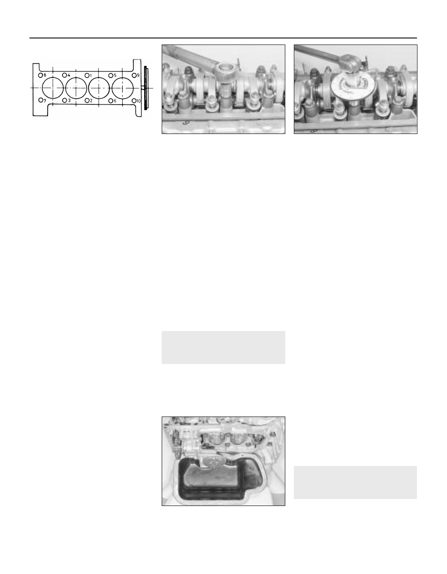
that an angle-measuring gauge is used during
this stage of the tightening, to ensure
accuracy (see illustration). If a gauge is not
available, use white paint to make alignment
marks between the bolt head and cylinder
head prior to tightening; the marks can then
be used to check that the bolt has been
rotated through the correct angle during
tightening.
39 On cast-iron block engines, it will then be
necessary to tighten the bolts through the
specified Stage 3 angle setting.
40 With the cylinder head bolts correctly
tightened, refit the dipstick tube retaining bolt
and tighten it securely.
41 Refit the timing belt to the camshaft
sprocket. Ensure that the “front run” of the
belt is taut - ie, ensure that any slack is on the
tensioner pulley side of the belt. Do not twist
the belt sharply while refitting it, and ensure
that the belt teeth are seated centrally in the
sprockets.
42 Loosen the tensioner pulley retaining nut.
Pivot the pulley anti-clockwise to remove all
free play from the timing belt, then retighten
the nut.
43 Tension the belt as described under the
relevant sub-heading in Section 6, then refit
the centre and upper timing belt covers as
described in Section 5.
Carburettor models
44 If the head was stripped for overhaul, refit
the distributor and HT coil as described in
Chapter 5, ensuring that the HT leads are
correctly reconnected. If the head was not
stripped, reconnect the wiring connector and
vacuum pipe to the distributor, and the HT
lead to the coil; clip the TDC sensor wiring
connector onto the coil bracket.
Fuel-injected models
45 If the head was stripped for overhaul, refit
the ignition HT coil and leads as described in
Chapter 5, ensuring that the leads are
correctly reconnected. If the head was not
stripped, simply reconnect the wiring
connector to the HT coil.
All models
46 Reconnect the wiring connector(s) to the
coolant switch/sensor(s) on the left-hand end
of the head.
47 Reconnect the coolant hoses to the
thermostat housing, securely tightening their
retaining clips.
48 Working as described in the relevant Part
of Chapter 4, carry out the following tasks:
a) Refit all disturbed wiring, hoses and
control cable(s) to the inlet manifold and
fuel system components.
b) On carburettor models, reconnect and
adjust the choke and accelerator cables.
c) On fuel injection models, reconnect and
adjust the accelerator cable.
d) Reconnect the exhaust system front pipe
to the manifold. Where applicable,
reconnect the lambda sensor wiring
connector.
e) Refit the air cleaner housing and inlet
duct.
49 Check and, if necessary, adjust the valve
clearances as described in Section 9.
50 On completion, reconnect the battery,
and refill the cooling system as described in
Chapter 1.
12 Sump - removal and refitting
2
Removal
1 Firmly apply the handbrake, then jack up
the front of the vehicle and support it on axle
stands (see “Jacking and Vehicle Support”).
Disconnect the battery negative lead.
2 Drain the engine oil, then clean and refit the
engine oil drain plug, tightening it to the
specified torque. If the engine is nearing its
service interval when the oil and filter are due
for renewal, it is recommended that the filter is
also removed, and a new one fitted. After
reassembly, the engine can then be refilled
with fresh oil. Refer to Chapter 1 for further
information.
3 Remove the exhaust system front pipe as
described in the relevant Part of Chapter 4.
4 Progressively slacken and remove all the
sump retaining nuts and bolts. On cast-iron
block engines, it may be necessary to unbolt
the flywheel cover plate from the transmission
to gain access to the left-hand sump bolts.
5 Break the joint by striking the sump with the
palm of your hand, then lower the sump and
withdraw it from underneath the vehicle (see
illustration).
6 While the sump is removed, take the
opportunity to check the oil pump pick-
up/strainer for signs of clogging or splitting. If
necessary, remove the pump as described in
Section 13, and clean or renew the strainer.
Refitting
7 Clean all traces of sealant from the mating
surfaces of the cylinder block/crankcase and
sump, then use a clean rag to wipe out the
sump and the engine’s interior.
8 Ensure that the sump and cylinder
block/crankcase mating surfaces are clean
and dry, then apply a coating of suitable
sealant to the sump mating surface.
9 Offer up the sump, locating it on its
retaining studs, and refit its retaining nuts and
bolts. Tighten the nuts and bolts evenly and
progressively to the specified torque.
10 Refit the exhaust front pipe as described
in the relevant Part of Chapter 4.
11 Replenish the engine oil (see Chapter 1).
13 Oil pump - removal,
inspection and refitting
3
Removal
1 Remove the sump (refer to Section 12).
2 Slacken and remove the three bolts
2A•12 TU engine in-car repair procedures
11.37a Cylinder head bolt tightening
sequence
11.38 . . . then through the angle
specified for stage 2
12.5 Slacken and remove the sump
retaining nuts and bolts, then remove
the sump from the engine
11.37b Working in the sequence shown,
tighten the head bolts first to the
stage 1 torque setting . . .