содержание .. 11 12 13 14 ..
Peugeot 405. Manual - part 13
flanged spacer, aligning its slot with the
Woodruff key.
25 Align the crankshaft sprocket slot with the
Woodruff key, and slide it onto the end of the
crankshaft.
26 Temporarily remove the locking pin from
the rear of the flywheel, then refit the
crankshaft sprocket retaining bolt and
washer. Tighten the bolt to the specified
torque, whilst preventing crankshaft rotation
using the method employed on removal. Refit
the locking pin to the rear of the flywheel.
27 Relocate the timing belt on the sprockets.
Ensure that the “front run” of the belt is taut -
ie, ensure that any slack is on the tensioner
pulley side of the belt. Do not twist the belt
sharply while refitting it, and ensure that the
belt teeth are seated centrally in the
sprockets.
28 Loosen the tensioner pulley retaining nut.
Rotate the pulley anti-clockwise to remove all
free play from the timing belt, then retighten
the nut.
29 Tension the belt as described in
paragraphs 14 to 19 of Section 6.
30 Refit the timing belt covers as described
in Section 5.
Tensioner pulley
31 Refit the tensioner pulley to its mounting
stud, and fit the retaining nut.
32 Ensure that the “front run” of the belt is
taut - ie, ensure that any slack is on the pulley
side of the belt. Check that the belt is centrally
located on all its sprockets. Rotate the pulley
anti-clockwise to remove all free play from the
timing belt, then tighten the pulley retaining
nut securely.
33 Tension the belt as described in
paragraphs 14 to 19 of Section 6.
34 Refit the timing belt covers as described
in Section 5.
8
Camshaft oil seal - renewal
4
Note: If the camshaft oil seal is to be renewed
with the timing belt still in place, check first
that the belt is free from oil contamination.
(Renew the belt as a matter of course if signs
of oil contamination are found; see Section 6.)
Cover the belt to protect it from oil
contamination while work is in progress.
Ensure that all traces of oil are removed from
the area before the belt is refitted.
1 Remove the camshaft sprocket as
described in Section 7.
2 Punch or drill two small holes opposite
each other in the oil seal. Screw a self-tapping
screw into each, and pull on the screws with
pliers to extract the seal.
3 Clean the seal housing, and polish off any
burrs or raised edges, which may have
caused the seal to fail in the first place.
4 Lubricate the lips of the new seal with clean
engine oil, and drive it into position until it
seats on its locating shoulder. Use a suitable
tubular drift, such as a socket, which bears
only on the hard outer edge of the seal. Take
care not to damage the seal lips during fitting.
Note that the seal lips should face inwards.
5 Refit the camshaft sprocket as described in
Section 7.
9
Valve clearances - checking
and adjustment
3
Note: The valve clearances must be checked
and adjusted only when the engine is cold.
1 The importance of having the valve
clearances correctly adjusted cannot be
overstressed, as they vitally affect the
performance of the engine. If the clearances
are too big, the engine will be noisy (charac-
teristic rattling or tapping noises) and engine
efficiency will be reduced, as the valves open
too late and close too early. A more serious
problem arises if the clearances are too small,
however. If this is the case, the valves may not
close fully when the engine is hot, resulting in
serious damage to the engine (eg. burnt valve
seats and/or cylinder head warping/cracking).
The clearances are checked and adjusted as
follows.
2 Remove the cylinder head cover and oil
baffle plate as described in Section 4.
3 The engine can now be turned using a
suitable socket and extension bar fitted to the
crankshaft sprocket/pulley bolt.
4 It is important that the clearance of each
valve is checked and adjusted only when the
valve is fully closed, with the rocker arm
resting on the heel of the cam (directly
opposite the peak). This can be ensured by
carrying out the adjustments in the following
sequence, noting that No 1 cylinder is at the
transmission end of the engine. The correct
valve clearances are given in the Specifica-
tions at the start of this Chapter. The valve
locations can be determined from the position
of the manifolds.
Valve fully
Adjust valves
open
No 1 exhaust
No 3 inlet and No 4 exhaust
No 3 exhaust
No 4 inlet and No 2 exhaust
No 4 exhaust
No 2 inlet and No 1 exhaust
No 2 exhaust
No 1 inlet and No 3 exhaust
5 With the relevant valve fully open, check the
clearances of the two valves specified.
Clearances are checked by inserting a feeler
blade of the correct thickness between the
valve stem and the rocker arm adjusting
screw. The feeler blade should be a light,
sliding fit. If adjustment is necessary, slacken
the adjusting screw locknut, and turn the
screw as necessary. Once the correct
clearance is obtained, hold the adjusting
screw and securely tighten the locknut.
Recheck the valve clearance, and adjust
again if necessary.
6 Rotate the crankshaft until the next valve in
the sequence is fully open, and check the
clearances of the next two specified valves.
7 Repeat the procedure until all eight valve
clearances have been checked (and if
necessary, adjusted), then refit the oil baffle
plate and cylinder head cover as described in
Section 4.
10 Camshaft and rocker arms -
removal, inspection and
refitting
4
General information
1 The rocker arm assembly is secured to the
top of the cylinder head by the cylinder head
bolts. Although in theory, it is possible to undo
the head bolts and remove the rocker arm
assembly without removing the head, in
practice, this is not recommended. Once the
bolts have been removed, the head gasket will
be disturbed, and the gasket will almost
certainly leak or blow after refitting. For this
reason, removal of the rocker arm assembly
cannot be done without removing the cylinder
head and renewing the head gasket.
2 The camshaft is slid out of the right-hand
end of the cylinder head, and it therefore
cannot be removed without first removing the
cylinder head, due to a lack of clearance.
Removal
Rocker arm assembly
3 Remove the cylinder head as described in
Section 11.
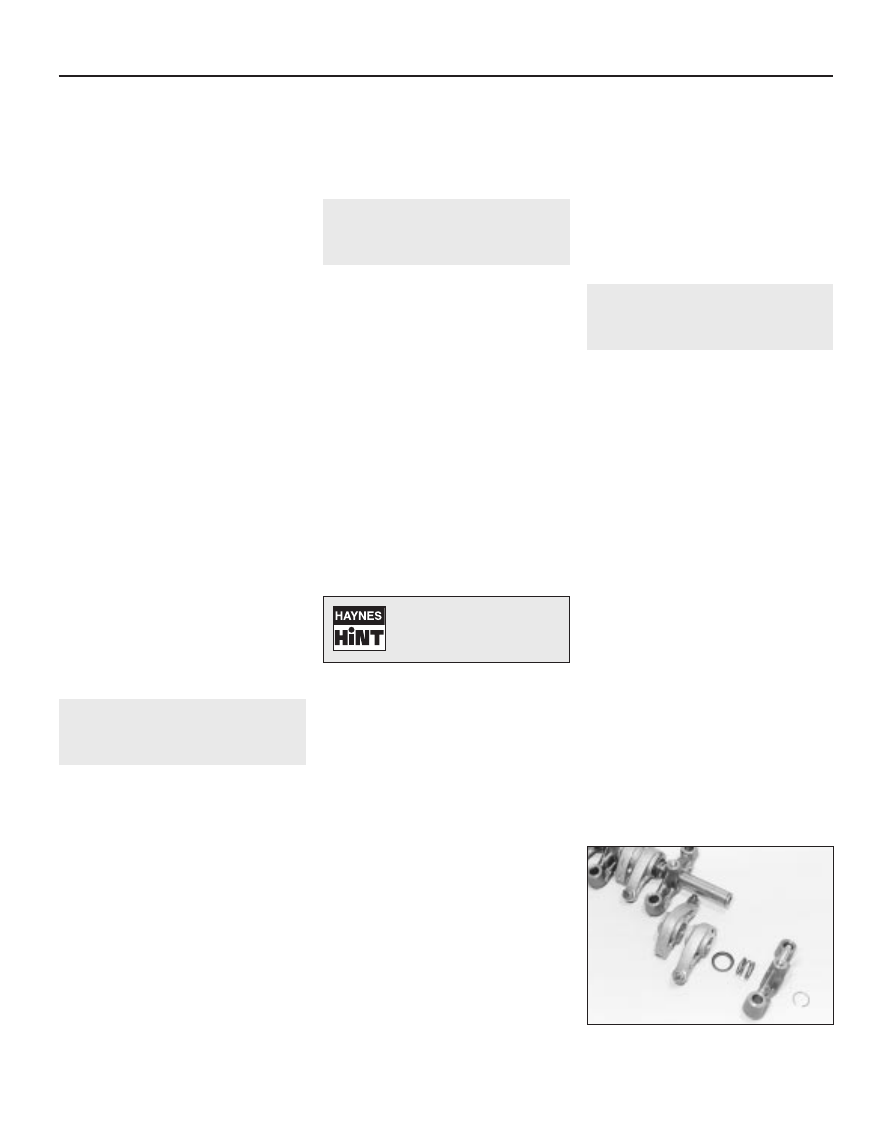
4 To dismantle the rocker arm assembly,
carefully prise off the circlip from the right-
hand end of the rocker shaft; retain the rocker
pedestal, to prevent it being sprung off the
end of the shaft. Slide the various
components off the end of the shaft, keeping
all components in their correct fitted order
(see illustration). Make a note of each
component’s correct fitted position and
orientation as it is removed, to ensure it is
fitted correctly on reassembly.
2A•8 TU engine in-car repair procedures
10.4 Remove the circlip, and slide the
components off the end of the rocker arm
Turning the engine will be
easier if the spark plugs are
removed first - see Chapter 1