содержание .. 10 11 12 13 ..
Peugeot 405. Manual - part 12
rotate the crankshaft slightly, to get the holes
to align.
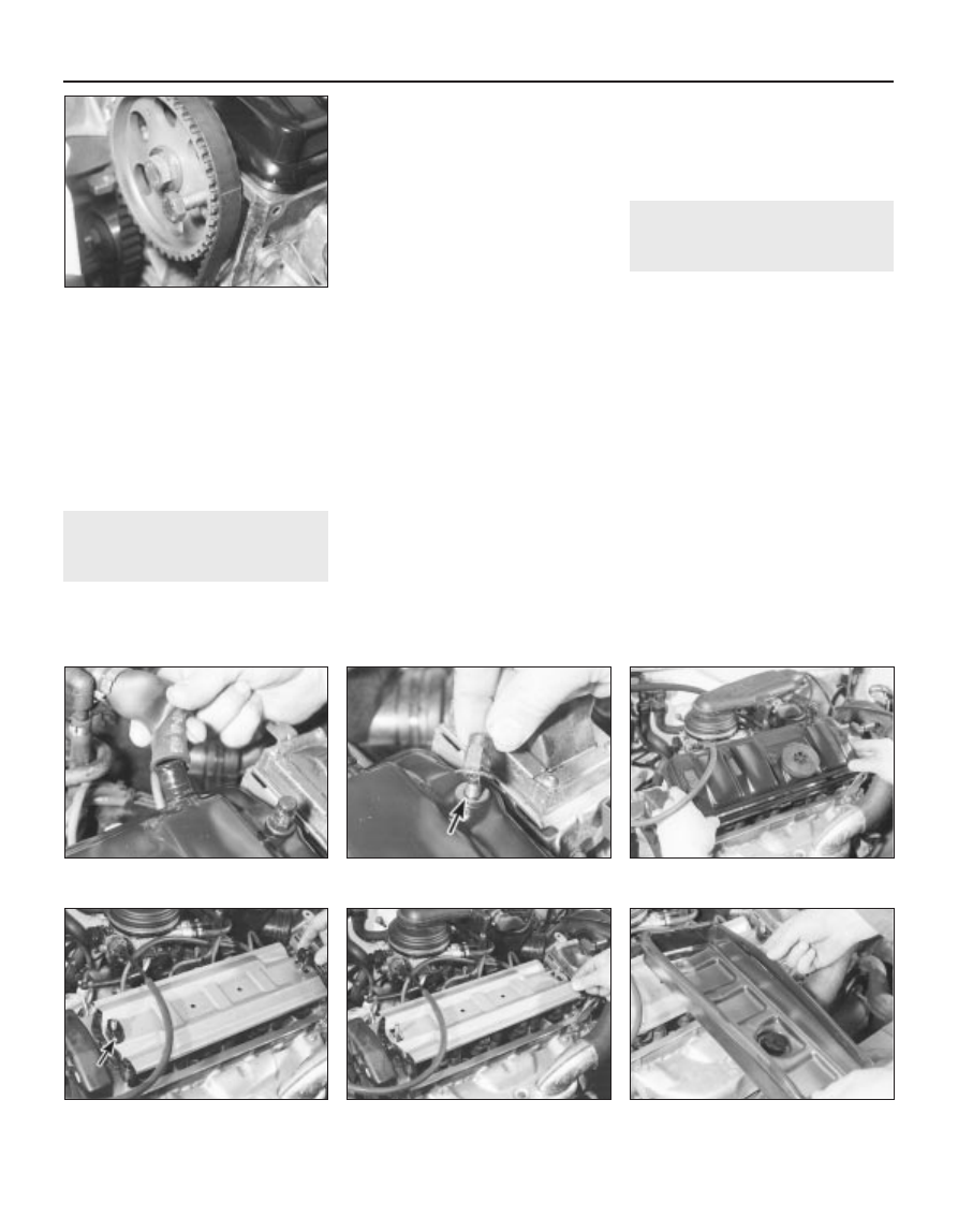
5 With the flywheel correctly positioned,
insert a 10 mm diameter bolt or a drill through
the timing hole in the camshaft sprocket, and
locate it in the hole in the cylinder head (see
illustration).
6 The crankshaft and camshaft are now
locked in position, preventing unnecessary
rotation.
4
Cylinder head cover -
removal and refitting
2
Removal
1 Disconnect the battery negative lead.
2 Where necessary, undo the bolts securing
the HT lead retaining clips to the rear of the
cylinder head cover, and position the clips
clear of the cover.
3 Slacken the retaining clip, and disconnect
the breather hose from the left-hand end of
the cylinder head cover (see illustration).
Where the original crimped-type Peugeot
hose clip is still fitted, cut it off and discard it.
Use a standard worm-drive clip on refitting.
4 Undo the two retaining nuts, and remove
the washer from each of the cylinder head
cover studs (see illustration).
5 Lift off the cylinder head cover, and remove
it along with its rubber seal (see illustration).
Examine the seal for signs of damage and
deterioration, and if necessary, renew it.
6 Lift off the spacer from each stud, and
remove the oil baffle plate (see illustrations).
Refitting
7 Carefully clean the cylinder head and cover
mating surfaces, and remove all traces of oil.
8 Fit the rubber seal over the edge of the
cylinder head cover, ensuring that it is
correctly located along its entire length (see
illustration).
9 Refit the oil baffle plate to the engine, and
locate the spacers in their recesses in the
baffle plate.
10 Carefully refit the cylinder head cover to
the engine, taking great care not to displace
the rubber seal.
11 Check that the seal is correctly located,
then refit the washers and cover retaining
nuts, and tighten them to the specified torque.
12 Where necessary, refit the HT lead clips to
the rear of the head cover, and securely
tighten their retaining bolts.
13 Reconnect the breather hose to the
cylinder head cover, securely tightening its
retaining clip, and reconnect the battery
negative lead.
5
Timing belt covers - removal
and refitting
2
Removal
Upper cover
1 Slacken and remove the two retaining bolts
(one at the front and one at the rear), and
remove the upper timing cover from the
cylinder head (see illustrations).
Centre cover
2 Remove the upper cover as described in
paragraph 1, then free the wiring from its clips
on the centre cover (see illustration).
3 Slacken and remove the three retaining
bolts (one at the rear of the cover, beneath the
engine mounting plate, and two directly above
the crankshaft pulley), and manoeuvre the
centre cover out from the engine
compartment
(see illustration).
Lower cover
4 Remove the auxiliary drivebelt as described
in Chapter 1.
5 Remove the upper and centre covers as
described in paragraphs 1 to 3.
4.8 On refitting, ensure the rubber seal is
located on the cylinder head cover
2A•4 TU engine in-car repair procedures
3.5 . . . then insert a 10 mm bolt through
the cam sprocket timing hole, and locate it
in the cylinder head
4.4 . . . then slacken and remove the cover
retaining nuts and washers (arrowed) . . .
4.6b . . . and remove the oil baffle plate
4.6a Lift off the spacers
(second one arrowed) . . .
4.5 . . . and lift off the cylinder head cover
4.3 Disconnect the breather hose from the
cylinder head cover . . .