Peugeot 405. Manual - part 17


  Главная      Peugeot     Peugeot 405 (1988-1997) - Service And Repair Manual Haynes


поиск по сайту            


содержание   ..  15  16  17  18   ..


Peugeot 405. Manual - part 17


28 Loosen the two front tensioner assembly
retaining bolts. Move the tensioner pulley
away from the belt, using the same square-
section key on the pulley backplate.
29 Check that the camshaft sprocket and
crankshaft locking pins are still in position,
then remove and inspect the timing belt as
described in paragraphs 11 and 12.

Refitting

Early (pre-1992) 1580 cc and 1905 cc
models with a semi-automatic belt
tensioner

30 Before refitting, thoroughly clean the
timing belt sprockets. Check that the
tensioner pulley rotates freely, without any
sign of roughness. If necessary, renew the
tensioner pulley as described in Section 8.
31 Ensure that the camshaft sprocket locking
pin is still in position. Temporarily refit the
crankshaft pulley, and insert the locking pin
through the pulley timing hole to ensure that
the crankshaft is still correctly positioned.
32 Remove the crankshaft pulley. Manoeuvre
the timing belt into position, ensuring that any
arrows on the belt are pointing in the direction
of rotation (clockwise when viewed from the
right-hand end of the engine).
33 Do not twist the timing belt sharply while
refitting it. Fit the belt over the crankshaft and
camshaft sprockets. Ensure that the belt
“front run” is taut - ie, any slack should be on
the tensioner pulley side of the belt. Fit the
belt over the water pump sprocket and
tensioner pulley. Ensure that the belt teeth are
seated centrally in the sprockets.
34 Slacken the tensioner cam spindle
locknut, and check that the tensioner pulley is
forced against the timing belt by spring
pressure.
35 Refit the crankshaft pulley, tightening its
retaining bolt by hand only.
36 Rotate the crankshaft through at least two
complete rotations in a clockwise direction
(viewed from the right-hand end of the
engine). Realign the camshaft and crankshaft
engine assembly/valve timing holes (see
Section 3). Do not at any time rotate the
crankshaft anti-clockwise. Both camshaft and
crankshaft timing holes should be aligned so
that the locking pins can be easily inserted.
This indicates that the valve timing is correct.
37 If the timing holes are not correctly
positioned, release the tensioner assembly as
described in paragraph 8, and disengage the
belt from the camshaft sprocket. Rotate the
camshaft and crankshaft slightly as required
until both locking pins are in position.
Relocate the timing belt on the camshaft
sprocket. Ensure that the belt “front run” is
taut - ie, that any slack is on the tensioner
pulley side of the belt. Slacken the tensioner
locknut, then remove the locking pins and
repeat the procedure in paragraph 36.
38 Once both timing holes are correctly
aligned, tighten the two tensioner assembly
retaining nuts to the specified torque. Tighten

the tensioner cam spindle locknut to its
specified torque.
39 With the belt correctly installed and
tensioned, where removed refit the engine
bracket to the side of the cylinder head/block,
and securely tighten its retaining bolts. Refit
the right-hand mounting bracket, and tighten
its retaining nuts to the specified torque. The
jack can then be removed from underneath
the engine.
40 Remove the crankshaft pulley, then refit
the timing belt covers (refer to Section 6).
41 Install the crankshaft pulley (Section 5),
and reconnect the battery negative terminal.

Later (1992-on) 1580 cc and 1905 cc
(8-valve) models with a manually-
adjusted belt tensioner pulley, and all
1761 cc and 1998 cc (8-valve) models

Note: Peugeot specify the use of a special
electronic tool (SEEM C. TRONIC belt tension
measuring tool) to correctly set the timing belt
tension. If this equipment is not available, an
approximate setting can be achieved using
the method described below. If this method is
used, however, the belt tension must be
checked using the special electronic tool at
the earliest possible opportunity. Do not drive
the vehicle over large distances, or use high
engine speeds, until the belt tension is known
to be correct. Refer to a Peugeot dealer for
advice.
42 Install the timing belt as described above
in paragraphs 30 to 33.
43 Loosen the tensioner pulley retaining bolt.
Using the square-section key, pivot the pulley
anti-clockwise to remove all free play from the
timing belt.
44 If the special belt tension measuring
equipment is available, it should be fitted to
the “front run” of the timing belt. The tensioner
roller should be adjusted so that the initial belt
tension is 16 ± 2 units on 1998 cc 8-valve
models, and 30 ± 2 units on all other models.
45 Tighten the pulley retaining bolt to the
specified torque. Refit the crankshaft pulley
again, tightening its bolt by hand only.
46 Carry out the operations described in
paragraph 36 (and where necessary, para-
graph 37, ignoring the information about the
tensioner) to ensure both timing holes are
correctly aligned and the valve timing is correct.
47 If the tension is being set without using
the special measuring tool, proceed as
follows. Check that, under moderate pressure
from the thumb and forefinger, the belt can
just be twisted through 90° at the mid-point of
the “front run” of the belt. Note that this
method is only an initial setting, and the belt
tension must checked at the earliest available
opportunity using the special measuring tool.
Failure to do so could lead to the belt
breaking (through over-tightening) or slipping
(through slackness), resulting in serious
engine damage. If necessary, readjust the
tensioner pulley position as required. Tighten
its retaining bolt to the specified torque on
completion.

48 If the special measuring tool is being
used, the final belt tension on the “front run”
of the belt on all models should be 44 ± 2
units. Readjust the tensioner pulley position
as required, then retighten the retaining bolt to
the specified torque. Rotate the crankshaft
through a further two rotations clockwise, and
recheck the tension. Repeat this procedure as
necessary until the correct tension reading is
obtained after rotating the crankshaft.
49 With the belt tension correctly set, on
1580 cc, 1761 cc and 1905 cc models, where
removed refit the engine bracket to the side of
the cylinder head/block, and securely tighten
its retaining bolts. Refit the right-hand engine
mounting bracket, and tighten its retaining
nuts to the specified torque. The jack can then
be removed from underneath the engine.
50 On all models, remove the crankshaft
pulley, then refit the timing belt cover(s) as
described in Section 6.
51 Refit the crankshaft pulley (Section 5), and
reconnect the battery negative terminal.

1905 cc 16-valve models

Note: Peugeot specify the use of a special
electronic tool (SEEM belt tension measuring
tool) to correctly set the timing belt tension. If
this equipment is not available, an
approximate setting can be achieved using
the method described below. If this method is
used, however, the tension must be checked
using the special electronic tool at the earliest
possible opportunity. Do not drive the vehicle
over large distances, or use high engine
speeds, until the belt tension is known to be
correct. Refer to a Peugeot dealer for advice.
52 Before refitting, thoroughly clean the
timing belt sprockets. Check that each
tensioner pulley rotates freely, without any
sign of roughness. If necessary, renew the
tensioner pulley(s) as described in Section 8.
53 Ensure that the camshaft and crankshaft
sprocket locking pins are still in position.
Slacken both tensioner mounting bolts so that
they are free to pivot easily.
54 Manoeuvre the timing belt into position,
ensuring that any arrows on the belt are
pointing in the direction of rotation (clockwise
when viewed from the right-hand end of the
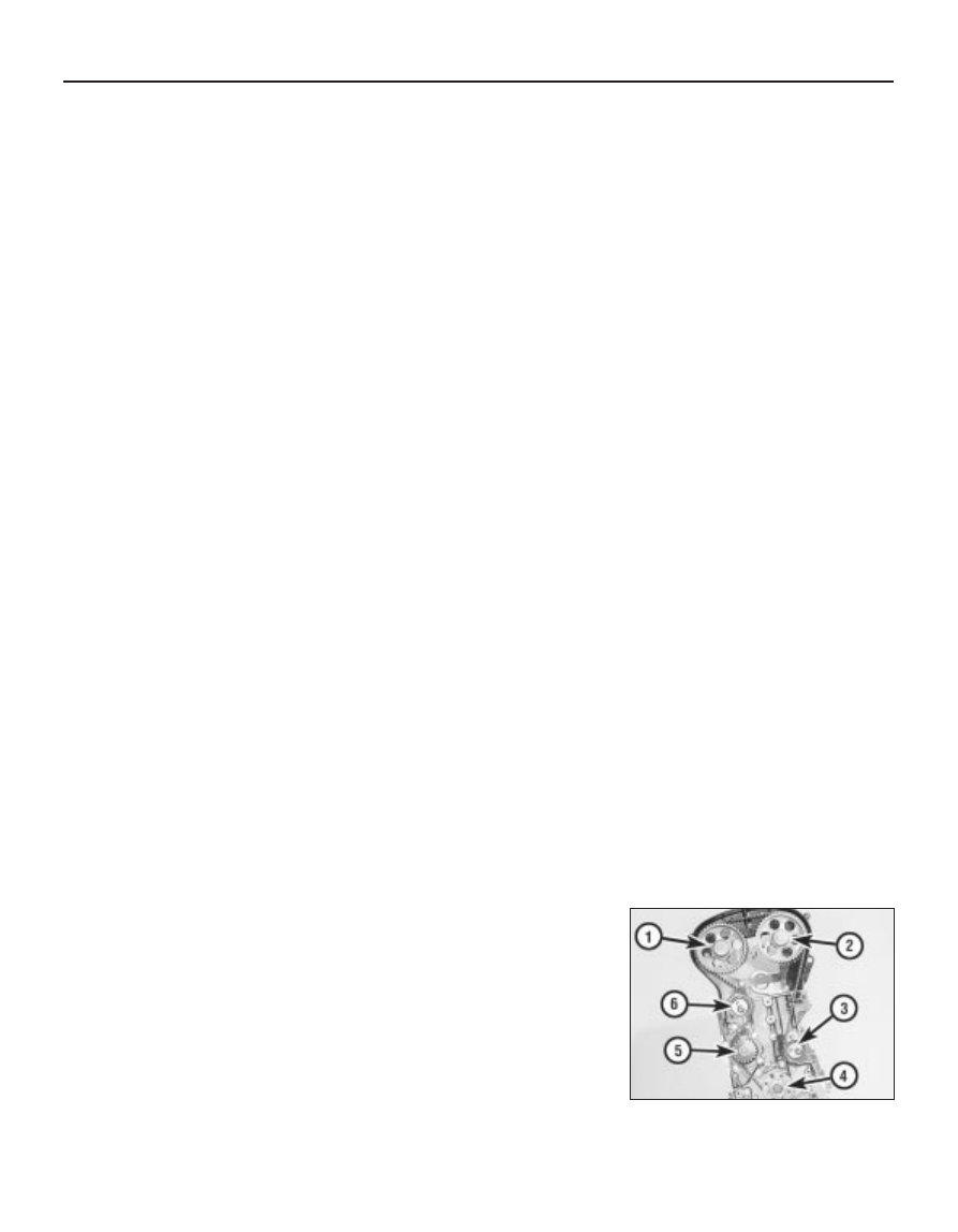
engine). Fit the timing belt in the sequence
given in the accompanying illustration (see
illustration)
.

2B•10 XU engine in-car repair procedures

7.54  Fit the timing belt in the sequence

given - 1905 cc 16-valve engines

55 Note that there may be timing marks on
the belt, in the form of yellow lines, to ensure it
is correctly positioned on both camshaft
sprockets and the crankshaft sprocket. The
two single-line timing marks should be aligned
with the timing dot (directly opposite the
sprocket timing hole) on each camshaft
sprocket. The double-line timing mark should
be aligned with the crankshaft sprocket,
where it will be directly opposite the sprocket
Woodruff key slot. Peugeot state that the use
of these timing marks is optional, but they are
useful in helping to ensure that the valve
timing is correctly set at the first attempt.
56 With the three locking pins in position,
move both the front and rear tensioner pulleys
towards the timing belt until both pulleys are
contacting the belt. Securely tighten the
retaining bolts.
57 If the tension is being set without the use
of the special measuring tool, proceed as
follows. Using the square-section key fitted to
the hole in the tensioner backplate, move the
front tensioner pulley against the belt until all
free play is removed from the belt. Hold the
tensioner in this position, and tighten the
pulley retaining bolts to the specified torque.
Similarly move the rear tensioner pulley
against the belt and tighten the bolt.
58 If the special belt tension measuring
equipment is available, it should be fitted to
the “front run” of the timing belt, between the
front tensioner and the camshaft sprocket.
Move the front tensioner pulley anti-clockwise
so that the belt is tensioned to a setting of 19
units, then tighten the retaining bolt to the
specified torque setting.
59 Slacken the rear tensioner pulley retaining
bolt. Using the square-section key, pivot the
pulley clockwise until the belt tension on the
“front run” is 21 units. Hold the tensioner in
position, and tighten its retaining bolt to the
specified torque setting.
60 Remove the locking pins from the
camshaft and crankshaft sprockets and,
where fitted, the tensioning measuring device
from the belt.
61 Rotate the crankshaft through at least two
complete rotations in a clockwise direction
(viewed from the right-hand end of the
engine). Realign the camshaft and crankshaft
engine assembly/valve timing holes (see
Section 3). Do not at any time rotate the
crankshaft anti-clockwise. Both camshaft
timing holes and the crankshaft timing hole
should be correctly positioned so that the
locking pins can be easily inserted, indicating
that the valve timing is correct.
62 If the timing holes are not correctly
positioned, repeat the tensioning procedure.
63 Once the valve timing is correctly set,
remove the locking pins and recheck the belt
tension.
64 If the tension is being set without the
special measuring tool, proceed as follows.
Check that, under moderate pressure from
the thumb and forefinger, the belt can just be
twisted through 45°, at the mid-point between

the camshaft sprocket and tensioner pulley on
the “front run” of the belt. Note that this
method is only an initial setting, and the belt
tension must be checked at the earliest
available opportunity using the special
measuring tool. Failure to do so could lead to
the belt breaking (through over-tightening) or
slipping (through slackness), resulting in
serious engine damage.
65 If the special measuring tool is being
used, the final belt tension on the “front run”
of the belt, between the camshaft sprocket
and tensioner pulley, should be 45 ± 5 units.
Repeat the procedure as necessary, until the
correct tension reading is obtained after the
crankshaft has been rotated.
66 Once the belt tension is correctly set, refit
the timing belt covers as described in 
Section 6. Refit the crankshaft pulley as
described in Section 5, and reconnect the
battery negative terminal

1998 cc 16-valve models

Note: Peugeot specify the use of a special
electronic tool (SEEM belt tension measuring
tool) to correctly set the timing belt tension. If
this equipment is not available, an
approximate setting can be achieved using
the method described below. If this method is
used, however, the tension must be checked
using the special electronic tool at the earliest
possible opportunity. Do not drive the vehicle
over large distances, or use high engine
speeds, until the belt tension is known to be
correct. Refer to a Peugeot dealer for advice.
67 Before refitting, thoroughly clean the
timing belt sprockets. Check that each
tensioner pulley rotates freely, without any
sign of roughness. If necessary, renew the
tensioner pulley(s) as described in Section 8.
68 Ensure that the camshaft and crankshaft
sprocket locking pins are still in position.
Slacken the tensioner mounting bolts so that
they are free to pivot easily.
69 Manoeuvre the timing belt into position,
ensuring that any arrows on the belt are
pointing in the direction of rotation (clockwise
when viewed from the right-hand end of the
engine).
70 Note that there are also timing marks on
the belt, in the form of yellow lines, to ensure it
is correctly positioned on both camshaft
sprockets and the crankshaft sprocket. The
two single-line timing marks should be aligned
with the timing dot (directly opposite the
sprocket timing hole) on each camshaft
sprocket. The double-line timing mark should
be aligned with the crankshaft sprocket,
where it will be directly opposite the sprocket
Woodruff key slot. Peugeot state that the use
of these timing marks is optional, but they are
useful in helping to ensure that the valve
timing is correctly set at the first attempt.
71 With the three locking pins in position,
move both the front and rear tensioner pulleys
towards the timing belt until both pulleys are
contacting the belt. Securely tighten the rear
tensioner retaining bolt.

72 If the tension is being set without the use
of the special measuring tool, proceed as
follows. Using the square-section key fitted to
the hole in the tensioner backplate, move the
front tensioner pulley against the belt until all
free play is removed from the belt. Hold the
tensioner in this position, and tighten the
pulley retaining bolts to the specified torque.
73 If the special belt tension measuring
equipment is available, it should be fitted to
the “front run” of the timing belt, between the
front tensioner and the camshaft sprocket.
Move the tensioner pulley backplate so that
the belt is initially over-tensioned to a setting
of 45 units, then back the tensioner off until
the belt tension is 22 ± 2 units. Hold the
backplate in this position, and tighten both the
tensioner pulley retaining bolts to the
specified torque.
74 Slacken the rear tensioner pulley retaining
bolt. Using the square-section key, pivot the
pulley anti-clockwise until all free play is
removed from the belt. If the belt tension
measuring equipment is being used, set the
tensioner pulley so that the belt tension on the
“front run” is 32 ± 2 units. Hold the tensioner
in position, and tighten its retaining bolt to the
specified torque setting.
75 Remove the locking pins from the
camshaft and crankshaft sprockets and,
where fitted, the tensioning measuring device
from the belt.
76 Rotate the crankshaft through at least two
complete rotations in a clockwise direction
(viewed from the right-hand end of the
engine). Realign the camshaft and crankshaft
engine assembly/valve timing holes (see
Section 3). Do not at any time rotate the
crankshaft anti-clockwise. Both camshaft
timing holes and the crankshaft timing hole
should be correctly positioned so that the
locking pins can be easily inserted, indicating
that the valve timing is correct.
77 If the timing holes are not correctly
positioned, slacken the tensioner assembly
retaining bolts, and disengage the belt from
the camshaft sprockets. Rotate the camshafts
and crankshaft slightly as required until all
locking pins are in position, then relocate the
timing belt on the camshaft sprocket. Ensure
that the belt “top run” and “front run” are taut
- ie, ensure that any slack is on the rear
tensioner pulley and water pump side of the
belt. Repeat the tensioning procedure until the
valve timing is correct.
78 Once the valve timing is correctly set,
remove the locking pins and recheck the belt
tension.
79 If the tension is being set without the
special measuring tool, proceed as follows.
Check that, under moderate pressure from
the thumb and forefinger, the belt can just be
twisted through 45°, at the mid-point between
the camshaft sprocket and tensioner pulley on
the “front run” of the belt. Note that this
method is only an initial setting, and the belt
tension must be checked at the earliest
available opportunity using the special

XU engine in-car repair procedures  2B•11

2B

measuring tool. Failure to do so could lead to
the belt breaking (through over-tightening) or
slipping (through slackness), resulting in
serious engine damage. If necessary, readjust
the rear tensioner pulley position as required,
and tighten its retaining bolt to the specified
torque.
80 If the special measuring tool is being
used, the final belt tension on the “front run”
of the belt, between the camshaft sprocket
and tensioner pulley, should be 53 ± 2 units.
Readjust the rear tensioner pulley position as
required, then retighten the retaining bolt to
the specified torque. Rotate the crankshaft
through a further two rotations clockwise, and
recheck the tension. Repeat this procedure as
necessary, until the correct tension reading is
obtained after the crankshaft has been
rotated.
81 Once the belt tension is correctly set, refit
the timing belt covers (see Section 6). Refit the
crankshaft pulley as described in Section 5,
and reconnect the battery negative terminal

8

Timing belt tensioner and
sprockets 
- removal,
inspection and refitting

4

Note: This Section describes the removal and
refitting of the components concerned as
individual operations - if more than one is to
be removed at the same time, start by
removing the timing belt as described in
Section 7; remove the actual component as
described below, ignoring the preliminary
dismantling steps.

Removal

Disconnect the battery negative lead.
Align the engine assembly/valve timing
holes as described in Section 3, locking the
camshaft sprocket(s) and the crankshaft
pulley in position, and proceed as described
under the relevant sub-heading. Do not
attempt to rotate the engine whilst the pins
are in position.

Camshaft sprocket - early (pre-1992)
1580 cc and 1905 cc 8-valve models
with a semi-automatic belt tensioner

Remove the centre timing belt cover as
described in Section 6.
Slacken (but do not remove) the two nuts
securing the tensioner assembly to the end of
the cylinder block. Loosen the tensioner cam
spindle locknut, located on the rear of cylinder
block flange.
Using a suitable open-ended spanner on
the square-section end of the tensioner cam
spindle, rotate the cam until the tensioner
spring is fully compressed and the belt
tension is relieved. Hold the cam in this
position, and securely tighten the locknut.
Remove the locking pin from the camshaft
sprocket. Disengage the timing belt from the
sprocket and position it clear, taking care not
to bend or twist the belt sharply.

Slacken the camshaft sprocket retaining
bolt and remove it, along with its washer. To
prevent the camshaft rotating as the bolt is
slackened, a sprocket holding tool will be
required. In the absence of the special
Peugeot tool, an acceptable substitute can be
fabricated from two lengths of steel strip (one
long, the other short) and three nuts and bolts,
as follows. One nut and bolt forms the pivot of
a forked tool, with the remaining two nuts and
bolts at the tips of the “forks” to engage with
the sprocket spokes, as shown in illustration
8.39.  Do not attempt to use the sprocket
locking pin to prevent the sprocket from
rotating whilst the bolt is slackened.
With the retaining bolt removed, slide the
sprocket off the end of the camshaft. If the
locating peg is a loose fit in the rear of the
sprocket, remove it for safe-keeping. Examine
the camshaft oil seal for signs of oil leakage
and, if necessary, renew it as described in
Section 9.

Camshaft sprocket - later (1992-on)
1580 cc and 1905 cc (8-valve) models
with a manually-adjusted belt
tensioner pulley, and all 1761 cc and
1998 cc (8-valve) models

On all except 1998 cc 8-valve models,
remove the centre timing belt cover as
described in Section 6.
10 Loosen the timing belt tensioner pulley
retaining bolt. Rotate the pulley in a clockwise
direction, using a suitable square-section key
fitted to the hole in the pulley hub, then
retighten the retaining bolt.
11 Remove the camshaft sprocket as
described above in paragraphs 6 to 8.

Camshaft sprocket(s) - 
1905 cc 16-valve models

12 With the timing covers removed, loosen
the timing belt front and rear tensioner pulley
retaining bolts. Pivot the front pulley in a
clockwise direction, using a suitable square-
section key fitted to the hole in the pulley hub,
then securely retighten the retaining bolt.
Similarly pivot the rear pulley in an anti-
clockwise direction and retighten the bolt.
13 Remove the camshaft sprocket retaining
bolt as described in paragraphs 6 and 7.
14 Slide the sprocket off the end of the
camshaft. If the Woodruff key is a loose fit in
the camshaft, remove it and store it with the
sprocket for safe-keeping. Examine the
camshaft oil seal for signs of oil leakage and,
if necessary, renew it (see Section 9).

Camshaft sprocket(s) - 1998 cc 16-
valve models

15 Loosen the timing belt rear tensioner
pulley retaining bolt. Pivot the pulley in a
clockwise direction, using a suitable square-
section key fitted to the hole in the pulley hub,
then securely retighten the retaining bolt.
16 Loosen the two front tensioner assembly
retaining bolts. Move the tensioner pulley
away from the belt, using the same square-
section key on the pulley backplate.

17 Remove the camshaft sprocket retaining
bolt as described in paragraphs 6 and 7.
18 Slide the sprocket off the end of the
camshaft. If the Woodruff key is a loose fit in
the camshaft, remove it and store it with the
sprocket for safe-keeping. Examine the
camshaft oil seal for signs of oil leakage and,
if necessary, renew it (see Section 9).

Crankshaft sprocket - 
1580 cc, 1761 cc, 1905 cc and 
1998 cc 8-valve models

19 Remove the centre and/or lower timing
belt cover(s) (as applicable) as described in
Section 6.
20 On early (pre-1992) 1580 cc and 1905 cc
models with a semi-automatic belt tensioner,
release the timing belt tensioner as described
above in paragraphs 4 and 5.
21 On later (1992-on) 1580 cc and 1905 cc
models with a manually-adjusted belt
tensioner pulley, and all 1761 cc and 1998 cc
8-valve models, release the timing belt
tensioner as described in paragraph 10.
22 Disengage the timing belt from the
crankshaft sprocket, and slide the sprocket
off the end of the crankshaft. Remove the
Woodruff key from the crankshaft, and store it
with the sprocket for safe-keeping. Where
necessary, also slide the flanged spacer
(where fitted) off the end of the crankshaft.
23 Examine the crankshaft oil seal for signs
of oil leakage and, if necessary, renew it as
described in Section 16.

Crankshaft sprocket - 
1905 cc and 1998 cc 16-valve models

24 Remove the lower timing belt cover as
described in Section 6.
25 Release the timing belt tensioners as
described above in paragraphs 12 or 15 and
16 (as applicable). Disengage the timing belt
from the crankshaft sprocket, and remove the
locking pin.
26 To prevent the crankshaft turning whilst
the sprocket retaining bolt is being slackened,
select 4th gear, and have an assistant apply
the brakes firmly. If the engine has been
removed from the vehicle, lock the flywheel
ring gear using the arrangement shown in
illustration 5.3 (Section 5). Do not be tempted
to use the locking pin to prevent the
crankshaft from rotating.
27 Unscrew the retaining bolt and washer,
then slide the sprocket off the end of the
crankshaft. If the Woodruff key is a loose fit in
the crankshaft, remove it and store it with the
sprocket for safe-keeping.
28 Where necessary, slide the flanged
spacer (where fitted) off the crankshaft.
29 Examine the crankshaft oil seal for signs
of oil leakage and, if necessary, renew it as
described in Section 16.

Tensioner assembly - early (pre-1992)
1580 cc and 1905 cc 8-valve models
with a semi-automatic belt tensioner

30 Remove the centre timing belt cover as
described in Section 6.

2B•12 XU engine in-car repair procedures

31 Slacken and remove the two nuts and
washers securing the tensioner assembly to
the end of the cylinder block. Carefully ease
the spring cover off its studs, taking care not
to allow the spring to fly out as the cover is
withdrawn. Remove the spring and cover from
the engine (see illustration).
32 Slacken and remove the tensioner cam
spindle locknut and washer, located on the
rear of cylinder block flange, and withdraw the
cam spindle.
33 The tensioner pulley and backplate
assembly can then be manoeuvred out from
behind the timing belt.

Tensioner pulley - later (1992-on) 
1580 cc and 1905 cc 8-valve models
with a manually-adjusted belt
tensioner pulley, and all 1761 cc and
1998 cc 8-valve models

34 On all except 1998 cc 8-valve models,
remove the centre timing belt cover as
described in Section 6.
35 Slacken and remove the timing belt
tensioner pulley retaining bolt, and slide the
pulley off its mounting stud. Examine the
mounting stud for signs of damage and if
necessary, renew it.

Tensioner pulleys - 
1905 cc 16-valve models

36 The front and rear tensioner pulleys are
removed as described above.

Tensioner pulleys - 
1998 cc 16-valve models

37 The rear tensioner pulley is removed as
described above.
38 To remove the front tensioner pulley,
slacken and remove the two bolts securing
the pulley backplate to the cylinder block, and
remove the assembly from the engine.

Inspection

39 Clean the camshaft/crankshaft sprockets
thoroughly, and renew any that show signs of
wear, damage or cracks.
40 Clean the tensioner assembly, but do not
use any strong solvent which may enter the
pulley bearing. Check that the pulley rotates
freely on the backplate, with no sign of
stiffness or free play. Renew the assembly if
there is any doubt about its condition, or if

there are any obvious signs of wear or
damage.
41 On early 1580 cc and 1905 cc models, the
tensioner spring should also be carefully
checked, as its condition is critical for the
correct tensioning of the timing belt. The only
way to check the spring tension is to compare
it with a new one; if there is any doubt as to its
condition, the spring should be renewed.

Refitting

Camshaft sprocket - early (pre-1992)
1580 cc and 1905 cc 8-valve models
with a semi-automatic belt tensioner

42 Refit the locating peg (where removed) to
the rear of the sprocket. Locate the sprocket
on the end of the camshaft, ensuring that the
locating peg is correctly engaged with the
cutout in the camshaft end.
43 Refit the sprocket retaining bolt and
washer, and tighten it to the specified torque.
Retain the sprocket with the tool used on
removal (see illustration).
44 Realign the hole in the camshaft sprocket
with the corresponding hole in the cylinder
head, and refit the locking pin. Check that the
crankshaft pulley locking pin is still in position.
45 Refit the timing belt to the camshaft
sprocket. Ensure that the “front run” of the
belt is taut - ie, that any slack is on the
tensioner pulley side of the belt. Do not twist
the belt sharply while refitting it, and ensure
that the belt teeth are seated centrally in the
sprockets.
46 Release the tensioner cam spindle
locknut, and check that the tensioner pulley is
forced against the timing belt under spring
pressure.
47 Tension the timing belt (see Section 7).
48 With the belt correctly tensioned, and the
tensioner retaining nuts and locknut tightened
to the specified torque setting, refit the timing
belt covers as described in Section 6.
Reconnect the battery on completion.

Camshaft sprocket - later (1992-on)
1580 cc and 1905 cc (8-valve) models
with a manually-adjusted belt
tensioner pulley, and all 1761 cc and
1998 cc (8-valve) models

49 Refit the camshaft sprocket as described
above.

50 With the timing belt correctly engaged on
the sprockets, tension the belt as described in
Section 7.
51 Once the belt is correctly tensioned, refit
the timing belt covers (see Section 6).

Camshaft sprocket(s) - 1905 cc and
1998 cc 16-valve models

52 Refit the Woodruff key to its slot in the
camshaft end. Slide on the sprocket, aligning
its slot with the Woodruff key.
53 Refit the sprocket retaining bolt and
washer. Tighten the bolt to the specified
torque, whilst retaining the sprocket with the
tool used on removal.
54 Realign the hole in the camshaft sprocket
with the corresponding hole in the cylinder
head, and refit the locking pin.
55 Relocate the timing belt on the camshaft
sprocket(s), and tension the timing belt as
described in Section 7.
56 Once the belt is correctly tensioned, refit
the timing belt cover (Section 6).

Crankshaft sprocket - 
1580 cc, 1761 cc, 1905 cc and 
1998 cc 8-valve models

57 Slide on the flanged spacer (where fitted),
and refit the Woodruff key to its slot in the
crankshaft end.
58 Slide on the crankshaft sprocket, aligning
its slot with the Woodruff key.
59 Ensure that the camshaft sprocket locking
pin is still in position. Temporarily refit the
crankshaft pulley, and insert the locking pin
through the pulley timing hole, to ensure that
the crankshaft is still correctly positioned.
60 Remove the crankshaft pulley. Engage the
timing belt with the crankshaft sprocket.
Ensure that the belt “front run” is taut - ie, that
any slack is on the tensioner pulley side of the
belt. Fit the belt over the water pump sprocket
and tensioner pulley. Do not twist the belt
sharply while refitting it, and ensure that the
belt teeth are seated centrally in the
sprockets.
61 On early (pre-1992) 1580 cc and 1905 cc
models with a semi-automatic tensioner,
release the tensioner cam spindle locknut,
checking that the tensioner pulley is forced
against the timing belt under spring pressure.
Tension the timing belt as described in
Section 7.
62 On later (1992-on) 1580 cc and 1905 cc
models with a manually-adjusted belt
tensioner pulley, and all 1761 cc and 1998 cc
8-valve models, tension the timing belt as
described in Section 7.
63 On all models, remove the crankshaft
pulley, then refit the timing belt cover(s) as
described in Section 6.
64 Refit the crankshaft pulley (Section 5), and
reconnect the battery negative terminal.

Crankshaft sprocket - 1905 cc and
1998 cc 16-valve models

65 Slide on the flanged spacer (where fitted),
and refit the Woodruff key to its slot in the
crankshaft end.

XU engine in-car repair procedures  2B•13

8.43  Using a home-made tool for retaining

the camshaft sprocket whilst the sprocket

bolt is tightened (TU engine shown)

8.31  Timing belt tensioner assembly

components - early 1580 cc 
and 1905 cc 8-valve models

2B


содержание   ..  15  16  17  18   ..