содержание .. 10 11 12 13 ..
Peugeot 205. Manual - part 12
2
Compression test -
description and interpretation
Refer to Part A, Section 3 but on engines
with a static distributorless ignition system,
disable the ignition by depressing the
retaining clip and disconnecting the wiring
connector from the ignition module.
3
Engine assembly/valve
timing holes - general
information and usage
Note: Do not attempt to rotate the engine
whilst the crankshaft/camshaft are locked in
position. If the engine is to be left in this state
for a long period of time, it is a good idea to
place warning notices inside the vehicle, and
in the engine compartment. This will reduce
the possibility of the engine being accidentally
cranked on the starter motor, which is likely to
cause damage with the locking pins in place.
1 On all models, timing holes are drilled in the
camshaft sprocket and in the rear of the
flywheel. The holes are used to ensure that the
crankshaft and camshaft are correctly
positioned when assembling the engine (to
prevent the valves contacting the pistons when
refitting the cylinder head), or refitting the
timing belt. When the timing holes are aligned
with access holes in the cylinder head and the
front of the cylinder block, suitable diameter
pins can be inserted to lock both the camshaft
and crankshaft in position, preventing them
from rotating. Proceed as follows.
2 Remove the timing belt upper cover as
described in Section 6.
3 The crankshaft must now be turned until
the timing hole in the camshaft sprocket is
aligned with the corresponding hole in the
cylinder head. The holes are aligned when the
camshaft sprocket hole is in the 2 o’clock
position, when viewed from the right-hand
end of the engine. The crankshaft can be
turned by using a spanner on the crankshaft
sprocket bolt, noting that it should always be
rotated in a clockwise direction (viewed from
the right-hand end of the engine).
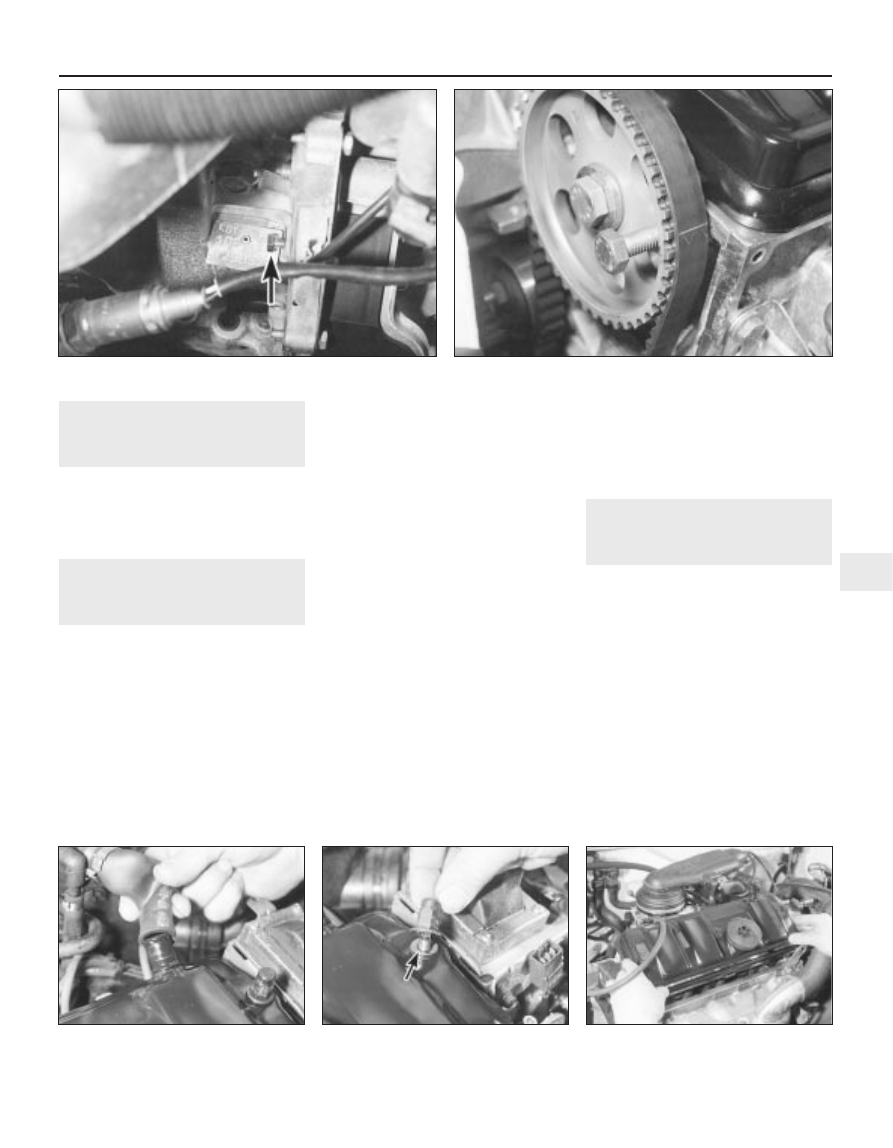
4 With the camshaft sprocket hole correctly
positioned, insert a 6 mm diameter bolt or drill
through the hole in the front, left-hand flange of
the cylinder block, and locate it in the timing
hole in the rear of the flywheel (see illustration).
Note that it may be necessary to rotate the
crankshaft slightly, to get the holes to align.
5 With the flywheel correctly positioned,
insert a 10 mm diameter bolt or a drill through
the timing hole in the camshaft sprocket, and
locate it in the hole in the cylinder head (see
illustration).
6 The crankshaft and camshaft are now
locked in position, preventing unnecessary
rotation.
4
Cylinder head cover -
removal and refitting
2
Removal
1 Disconnect the battery negative lead.
2 Where necessary, undo the bolts securing
the HT lead retaining clips to the rear of the
cylinder head cover, and position the clips
clear of the cover.
3 Slacken the retaining clip, and disconnect
the breather hose from the left-hand end of
the cylinder head cover (see illustration).
Where the original crimped-type Peugeot
hose clip is still fitted, cut it off and discard it.
Use a standard worm-drive clip on refitting.
4 Undo the two retaining nuts, and remove
the washer from each of the cylinder head
cover studs (see illustration).
5 Lift off the cylinder head cover, and remove
it along with its rubber seal (see illustration).
TU series engine in-car repair procedures 2C•3
2C
4.3 Disconnect the breather hose from the
cylinder head cover . . .
4.4 . . . then slacken and remove the cover
retaining nuts and washers (arrowed) . . .
4.5 . . . and lift off the cylinder head cover
3.4 Insert a 6 mm bolt (arrowed) through hole in cylinder block
flange and into timing hole in flywheel . . .
3.5 . . . then insert a 10 mm bolt through the camshaft sprocket
timing hole, and locate it in the cylinder head