Peugeot 205. Manual - part 10


  Главная      Peugeot     Peugeot 205 - Service And Repair Manual Haynes


поиск по сайту            


содержание   ..  8  9  10  11   ..


Peugeot 205. Manual - part 10


7

Camshaft and followers -
removal, inspection and
refitting

4

Removal

Remove the camshaft sprocket as
described in Section 5. Remove the rear cover
plate behind the sprocket.
Remove the camshaft cover. For ease of
access, remove the distributor cap and HT
leads, air cleaner assembly and brake servo
vacuum hose. 
Remove the distributor as described in
Chapter 5B.
Carefully ease the oil supply pipe out from
the top of the camshaft bearing caps, and
remove it. Note the O-ring seals fitted to each
of the pipe unions on later models.
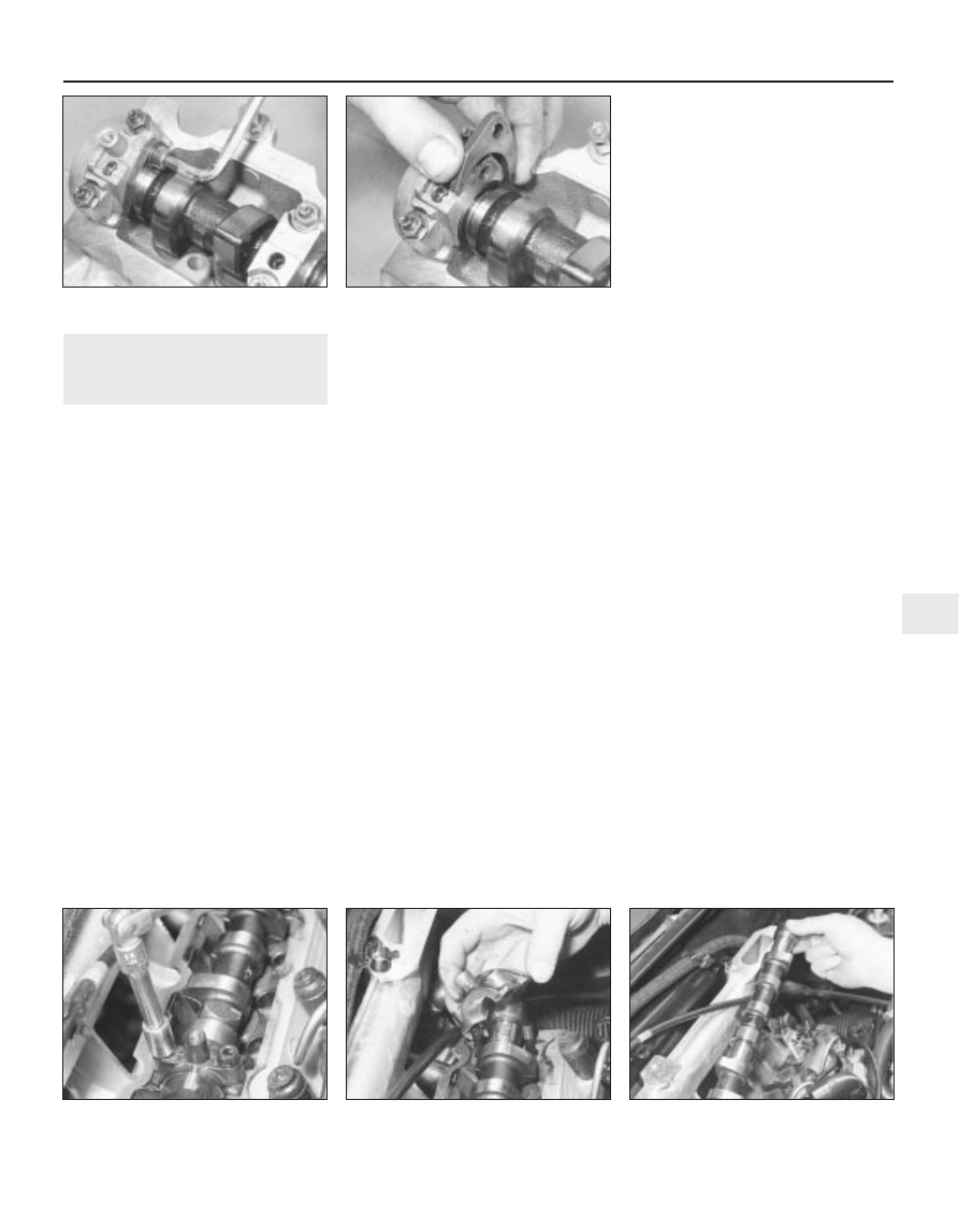
Where fitted undo the bolt and remove the
camshaft thrust plate (see illustrations).
The camshaft bearing caps should be
numbered 1 to 5, number 1 being at the
transmission end of the engine. If not, make
identification marks on the caps, using white
paint or a suitable marker pen. Also mark
each cap in some way to indicate its correct
fitted orientation. This will avoid the possibility
of installing the caps the wrong way around
on refitting.
Evenly and progressively slacken the
camshaft bearing cap retaining nuts by one
turn at a time. This will relieve the valve spring
pressure on the bearing caps gradually and
evenly. Once the pressure has been relieved,

the nuts can be fully unscrewed and removed
(see illustration).
Note the correct fitted orientation of the
bearing caps, then remove them from the
cylinder head (see illustration).
Lift the camshaft away from the cylinder
head, and slide the oil seal off the camshaft
end (see illustration).
10 Obtain eight small, clean plastic
containers, and number them 1 to 8;
alternatively, divide a larger container into
eight compartments. Using a rubber sucker,
withdraw each follower in turn, and place it in
its respective container. Do not interchange
the cam followers, or the rate of wear will be
much-increased. If necessary, also remove
the shim from the top of the valve stem, and
store it with its respective follower. Note that
the shim may stick to the inside of the follower
as it is withdrawn. If this happens, take care
not to allow it to drop out as the follower is
removed.

Inspection

11 Examine the camshaft bearing surfaces
and cam lobes for signs of wear ridges and
scoring. Renew the camshaft if any of these
conditions are apparent. Examine the
condition of the bearing surfaces, both on the
camshaft journals and in the cylinder
head/bearing caps. If the head bearing
surfaces are worn excessively, the cylinder
head will need to be renewed.
12 Examine the cam follower bearing
surfaces which contact the camshaft lobes for
wear ridges and scoring. Renew any follower

on which these conditions are apparent. If a
follower bearing surface is badly scored, also
examine the corresponding lobe on the
camshaft for wear, as it is likely that both will
be worn. Renew worn components as
necessary.

Refitting

13 Where removed, refit each shim to the top
of its original valve stem. Do not interchange
the shims, as this will upset the valve
clearances (see Section 2).
14 Liberally oil the cylinder head cam
follower bores and the followers. Carefully
refit the followers to the cylinder head,
ensuring that each follower is refitted to its
original bore. Some care will be required to
enter the followers squarely into their bores.
15 Liberally oil the camshaft bearings and
lobes, then refit the camshaft to the cylinder
head. Temporarily refit the sprocket to the end
of the shaft, and position it so that the
sprocket timing hole is aligned with the
corresponding cut-out in the cylinder head.
Also ensure that the crankshaft is still locked
in the timing position (see Section 4).
16 Ensure that the bearing cap and head
mating surfaces are completely clean,
unmarked, and free from oil. Refit all the caps,
using the identification marks noted on
removal to ensure that each is installed
correctly and in its original location.
17 Evenly and progressively tighten the
camshaft bearing cap nuts by one turn at a
time until the caps touch the cylinder head.
Then go round again and tighten all the nuts
to the specified torque setting. Work only as
described, to impose the pressure of the valve
springs gradually and evenly on the bearing
caps.
18 Where applicable, refit the camshaft
thrust plate and secure with its retaining bolt.
19 Examine the oil supply pipe union O-rings
(where fitted) for signs of damage or
deterioration, and renew as necessary. Apply
a smear of clean engine oil to the O-rings.
Ease the pipe into position in the top of the
bearing caps, taking great care not to
displace the O-rings.
20 Refit the distributor as described in
Chapter 5B.

XU series engine in-car repair procedures  2B•7

2B

7.5a  Removing the camshaft thrust plate

bolt . . .

7.5b  . . . followed by the thrust plate

7.7  Progressively unscrew the camshaft

bearing cap nuts . . .

7.8  . . . and remove the caps

7.9  Lift the camshaft from the cylinder

head

21 Fit a new camshaft oil seal, using the
information given in Section 6, then refit the
sprocket rear cover plate. Align the cover
plate using a 10 mm dowel or drill bit then
secure with the retaining bolt (see
illustration)
.
22 Refit the camshaft sprocket as described
in Section 5.
23 Check the valve clearances as described
in Section 2.
24 Refit the camshaft cover, HT leads and
distributor cap, air cleaner, and brake servo
vacuum hose.
25 Reconnect the battery negative terminal.

8

Cylinder head - removal and
refitting

4

Removal

Drain the cooling system as described in
Chapter 1. 
Remove the timing belt as described in
Section 4. 
Slacken, but do not remove, the engine
lower mounting rubber centre nut and bolt
(see illustration).
Remove the air cleaner assembly, inlet
ducts and pipes with reference to the relevant
Part of Chapter 4.
Remove the crankcase breather and its
pipes.
Remove the nut which secures the engine
right-hand mounting rubber to the cylinder
head bracket (see illustration).

Carefully raise the engine 60 to 80 mm
using a hoist or a well-protected jack. Remove
the two bolts which secure the right-hand
mounting bracket to the cylinder head, then
lower the engine back into position.
Remove the inlet manifold and associated
fuel system components with reference to the
relevant Part of Chapter 4.
Make suitable notes as an aid to refitting
then disconnect all coolant and vacuum
hoses and electrical leads from the cylinder
head.
10 Disconnect the exhaust downpipe(s) at
the manifold flange.
11 Remove the coolant pipe from the pump
inlet housing. Also remove the diagnostic
socket from its bracket.
12 Remove the camshaft cover, at the same
time removing the distributor cap and HT
leads. If the cylinder head is to be dismantled
for overhaul, remove the distributor or, on
models with static distributorless ignition
systems, the ignition module, as described in
Chapter 5B.
13 Working in the reverse of the sequence
shown in illustration 8.27, progressively
slacken the cylinder head bolts by half a turn
at a time, until all bolts can be unscrewed by
hand. Remove the bolts along with their
washers, noting the correct location of the
spacer fitted to the front right-hand bolt.
14 With all the cylinder head bolts removed,
the joint between the cylinder head and
gasket and the cylinder block/crankcase must
now be broken without disturbing the wet
liners. Although these liners are better-located
and sealed than some wet-liner engines, there
is still a risk of coolant and foreign matter
leaking into the sump if the cylinder head is
lifted carelessly. If care is not taken and the
liners are moved, there is also a possibility of
the bottom seals being disturbed, causing
leakage after refitting the head.
15 To break the joint, obtain two L-shaped
metal bars which fit into the cylinder head bolt
holes, and gently “rock” the cylinder head free
towards the front of the car. Do not try to
swivel the head on the cylinder
block/crankcase; it is located by dowels, as
well as by the tops of the liners.
16 When the joint is broken, lift the cylinder
head away. Remove the gasket from the top

of the block, noting the two locating dowels. If
the locating dowels are a loose fit, remove
them and store them with the head for safe-
keeping.
17 Do not attempt to turn the crankshaft with
the cylinder head removed, otherwise the wet
liners may be displaced. Operations that
require the crankshaft to be turned (eg
cleaning the piston crowns), should only be
carried out once the cylinder liners are firmly
clamped in position. In the absence of the
special Peugeot liner clamps, the liners can
be clamped in position as follows. Use large
flat washers positioned underneath suitable-
length bolts, or temporarily refit the original
head bolts, with suitable spacers fitted to their
shanks (see illustration).
18 If the cylinder head is to be dismantled for
overhaul, remove the camshaft and cam
followers as described in Section 7, then refer
to Part D of this Chapter.

Preparation for refitting

19 The mating faces of the cylinder head and
cylinder block/crankcase must be perfectly
clean before refitting the head. Use a hard
plastic or wood scraper to remove all traces of
gasket and carbon; also clean the piston
crowns. Refer to paragraph 17 before turning
the crankshaft. Take particular care during the
cleaning operations, as aluminium alloy is
easily damaged. Also, make sure that the
carbon is not allowed to enter the oil and
water passages - this is particularly important
for the lubrication system, as carbon could
block the oil supply to the engine’s
components. Using adhesive tape and paper,
seal the water, oil and bolt holes in the
cylinder block/crankcase. To prevent carbon
entering the gap between the pistons and
bores, smear a little grease in the gap. After
cleaning each piston, use a small brush to
remove all traces of grease and carbon from
the gap, then wipe away the remainder with a
clean rag. Clean all the pistons in the same
way.
20 Check the mating surfaces of the cylinder
block/crankcase and the cylinder head for
nicks, deep scratches and other damage. If
slight, they may be removed carefully with a
file, but if excessive, machining may be the
only alternative to renewal.

2B•8 XU series engine in-car repair procedures

7.21  Align the camshaft sprocket cover

plate using a dowel or twist drill

8.3  Engine lower mounting

8.6  Right-hand engine mounting and

cylinder head bracket

8.17  Cylinder liners clamped with washers

and bolts

21 If warpage of the cylinder head gasket
surface is suspected, use a straight-edge to
check it for distortion. Refer to Part D of this
Chapter if necessary.
22 Check the condition of the cylinder head
bolts, and particularly their threads, whenever
they are removed. Wash the bolts in suitable
solvent, and wipe them dry. Check each for
any sign of visible wear or damage, renewing
any bolt if necessary. Measure the length of
each bolt, to check for stretching (although
this is not a conclusive test, in the event that
all ten bolts have stretched by the same
amount). Although Peugeot do not actually
specify that the bolts must be renewed, it is
strongly recommended that the bolts should
be renewed as a complete set whenever they
are disturbed.
23 Note that as from early 1987, the cylinder
head bolts are of No 55 Torx type and 8 mm
thick washers are fitted to these bolts,
whereas 3 mm thick washers fitted to the
earlier type hexagon head bolts (see
illustration)
. The spacer fitted to the bolt at
the timing belt end is 25 mm thick, (previously
23 mm), and is identified by a groove around
its perimeter. A modified cylinder head gasket
is also fitted to engines with Torx type cylinder
head bolts, so it is important to quote the
engine number accurately when obtaining a
new one.

Refitting

24 Commence refitting by fitting the dowels to
the cylinder block. Keep the flywheel-end dowel
raised by inserting a 5 mm punch or large nail
through the hole in the front of the block (see
illustration)
. Remove the liner clamps.
25 Fit the new gasket, dry, with the tab at the
flywheel end. Lower the cylinder head into
position, making sure that it mates with the
dowels. Remove the punch or nail.
26 Fit the cylinder head bolts, their threads
clean and lightly oiled. Remember to fit the
spacer to the bolt at the timing belt end. When
fitting the Torx type cylinder head bolts, apply
a little molybdenum disulphide grease to their
heads, and to the contact surface of their
heads.
27 Progressively tighten the bolts in the order
shown to the Stage 1 specified torque setting
(see illustration). Note that the torque
settings are different for the two cylinder head
bolt types; ensure that the correct setting is
being used according to bolt type.
28 Raise the engine slightly and refit the two
bolts which secure the right-hand mounting
bracket to the cylinder head. Tighten these
bolts and slacken the one which holds the
same bracket to the engine block. Lower the
engine and tighten the right-hand mounting nut
and the lower mounting rubber nut and bolt.

Engines with hexagon head type
cylinder head bolts

29 Slacken cylinder head bolt No 1, then
immediately retighten it to the Stage 2
specified torque. Tighten further by the angle
specified for Stage 3 using a socket and
extension bar. It is recommended that an
angle-measuring gauge is used during this
stage of tightening, to ensure accuracy (see
illustration)
. Repeat for all the bolts, following
the tightening sequence.
30 Check the valve clearances and adjust, if
necessary (see Section 2).
31 Refit the remaining components in the
reverse order of removal. Make sure that the
correct inlet manifold gasket is fitted. A gasket
for carburettor versions is included in the
gasket overhaul set which is not the same as
the one for fuel injection models.
32 Refill and bleed the cooling system
(Chapter 1).
33 Start the engine and warm it up until the
cooling fan cuts in, then switch off and allow it
to cool for at least two hours.
34 Retighten the cylinder head bolts, as
described in paragraph 29, then recheck the
valve clearances.
35 If a new timing belt has been fitted, refer
to Section 4 and retension it if necessary.
36 Tighten the engine mounting bracket bolt.

Engines with Torx type cylinder head
bolts

37 Fully slacken all the head bolts, working in
the reverse of the tightening sequence. Once
the bolts are loose, tighten all bolts to their
Stage 2 specified torque setting, again
following the specified sequence.
38 With all the bolts tightened to their Stage 2
setting, working again in the specified
sequence, angle-tighten the bolts through the
specified Stage 3 angle, using a socket and
extension bar. It is recommended that an
angle-measuring gauge is used during this
stage of tightening, to ensure accuracy. Note
that no further tightening of the Torx type head
bolts is necessary.

XU series engine in-car repair procedures  2B•9

2B

8.23  Torx type cylinder head bolts fitted to

later models

8.24  Using a nail to hold the cylinder block

dowel in the raised position

8.27  Cylinder head bolt tightening sequence

8.29  Home-made torque angle measuring gauge. Disc is fixed

and pointer rotates

39 Check the valve clearances and adjust, if
necessary (see Section 2).
40 Refit the remaining components in the
reverse order of removal and with reference to
the relevant Sections and Chapters of this
manual as applicable. Make sure that the
correct inlet manifold gasket is fitted. A gasket
for carburettor versions is included in the
gasket overhaul set which is not the same as
the one for fuel injection models.
41 Refill and bleed the cooling system
(Chapter 1).
42 If a new timing belt has been fitted, refer
to Section 4 and retension it if necessary.
43 Tighten the engine mounting bracket bolt.

9

Sump - removal and refitting

3

Removal

Disconnect the battery negative lead.
Drain the engine oil, then clean and refit the
engine oil drain plug, tightening it securely. If
the engine is nearing its service interval when
the oil and filter are due for renewal, it is
recommended that the filter is also removed,
and a new one fitted. After reassembly, the
engine can then be refilled with fresh oil. Refer
to Chapter 1 for further information.
Chock the rear wheels then jack up the
front of the car and support it on axle stands
(see “Jacking and vehicle support”).
On models with air conditioning, where the
compressor is mounted onto the side of the
sump, remove the drivebelt as described in
Chapter 1. Unbolt the compressor, and
position it clear of the sump. Support the
weight of the compressor by tying it to the
vehicle, to prevent any excess strain being
placed on the compressor lines. Do not
disconnect the refrigerant lines from the
compressor (refer to the warnings given in
Chapter 3).
Disconnect the wiring to the oil level sensor
and the hose to the crankcase ventilation
system suction drain pipe on models so
equipped.
Progressively slacken and remove all the
sump retaining bolts. Since the sump bolts
vary in length and type, remove each bolt in
turn, and store it in its correct fitted order by
pushing it through a clearly-marked
cardboard template. This will avoid the
possibility of installing the bolts in the wrong
locations on refitting.
Break the joint by striking the sump with the
palm of your hand. Lower the sump, and
withdraw it from underneath the vehicle.
Remove the gasket (where fitted), and discard
it; a new one must be used on refitting. While
the sump is removed, take the opportunity to
check the oil pump pick-up/strainer for signs
of clogging or splitting. If necessary, remove
the pump as described in Section 10, and
clean or renew the strainer.

On some models, a large spacer plate is
fitted between the sump and the base of the
cylinder block/crankcase (see illustration). If
this plate is fitted, undo the two retaining
screws from diagonally-opposite corners of
the plate. Remove the plate from the base of
the engine, noting which way round it is fitted.

Refitting

Clean all traces of sealant/gasket from the
mating surfaces of the cylinder
block/crankcase and sump, then use a clean
rag to wipe out the sump and the engine’s
interior.
10 Where a spacer plate is fitted, remove all
traces of sealant/gasket from the spacer
plate, then apply a thin coating of silicone
sealant to the plate upper mating surface.
Offer up the plate to the base of the cylinder
block/crankcase, and securely tighten its
retaining screws (see illustration).
11 On models where the sump was fitted
without a gasket, ensure that the sump mating
surfaces are clean and dry, then apply a thin
coating of suitable sealant to the sump mating
surface.
12 On models where the sump was fitted
with a gasket, ensure that all traces of the old

gasket have been removed, and that the
sump mating surfaces are clean and dry.
Position the new gasket on the top of the
sump, using a dab of grease to hold it in
position.
13 Offer up the sump to the cylinder
block/crankcase. Refit its retaining bolts,
ensuring that each is screwed into its original
location. Tighten the bolts evenly and
progressively to the specified torque setting.
14 Where necessary, align the air
conditioning compressor with its mountings
on the sump, and insert the retaining bolts.
Securely tighten the compressor retaining
bolts, then refit the drivebelt as described in
Chapter 1.
15 Reconnect the wiring connector to the oil
level sensor (where fitted).
16 Lower the vehicle to the ground, then refill
the engine with oil as described in Chapter 1.

10 Oil pump - removal,

inspection and refitting

3

Removal

Remove the sump as described in Sec-
tion 9.
Where necessary, undo the two retaining
screws, and slide the sprocket cover off the
front of the oil pump.
Slacken and remove the three bolts
securing the oil pump to the base of the
cylinder block/crankcase. Disengage the
pump sprocket from the chain, and remove
the oil pump (see illustration). Where
necessary, also remove the spacer plate
which is fitted behind the oil pump on some
engines.

Inspection

Examine the oil pump sprocket for signs of
damage and wear, such as chipped or
missing teeth. If the sprocket is worn, the
pump assembly must be renewed, since the
sprocket is not available separately. It is also
recommended that the chain and drive
sprocket, fitted to the crankshaft, be renewed
at the same time. To renew the chain and
drive sprocket, first remove the crankshaft
timing belt sprocket as described in Section 5.

2B•10 XU series engine in-car repair procedures

9.10  Applying sealant to the sump spacer

plate upper surface

10.3  Removing the oil pump

9.8  Sump spacer plate (1) fitted to certain

models


содержание   ..  8  9  10  11   ..