Opel Frontera UBS. Manual - part 962
2A – 66 SUPPLEMENTAL RESTRAINT SYSTEM STEERING WHEEL & COLUMN
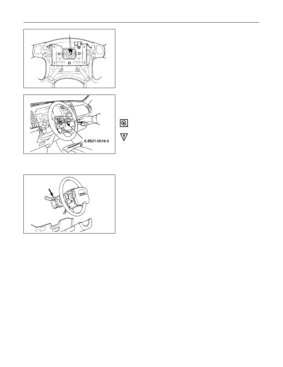
5. Steering Wheel
Apply a setting mark across the steering wheel and
shaft so parts can be reassembled in their original
position.
Use special tool. Remove the steering wheel.
Move the tires to the straight ahead position before
removing the steering wheel.
Steering wheel remover: 5-8840-0016-0 (J-29752)
CAUTION:
Never apply force to the steering wheel in direction of
the shaft by using a hammer or other impact tools in an
attempt to remove the steering wheel. The steering
shaft is designed as an energy absorbing unit.
6. Steering Column Cover
7. Combination Switch and SRS Coil Assembly
1)
Disconnect the wiring harness connectors
located under the steering column.
2)
Remove the combination switch assembly with
SRS coil.
NOTE:
The SRS coil is a part of the combination switch
assembly, which can not be replaced separately.
Therefore, be sure not to remove the SRS coil from
the combination switch assembly.
8. Snap Ring
9. Cushion Rubber
10. Shift Lock Cable (for A/T)
11. Lock Cylinder Assembly
Disconnect the starter switch harness connector
located under the steering column.
825RS046
430RS004
Setting mark