Opel Frontera UBS. Manual - part 963


  Index      Opel     Opel Frontera UBS - service repair manual 1998-2002 year


Search            


Content   ..  961  962  963  964   ..


Opel Frontera UBS. Manual - part 963


2A – 70 SUPPLEMENTAL RESTRAINT SYSTEM STEERING WHEEL & COLUMN

REMOVAL

Preparation:

1) Turn the steering wheel so that the vehicle's wheels

are pointing straight ahead.

2) Turn the ignition switch to "LOCK".

3) Disconnect the battery ground cable, and wait at least

5 minutes.

4) Disconnect the yellow 2way SRS connector located

under the steering column.

CAUTION:
The wheels of the vehicle must be straight ahead and the
steering column in the "LOCK" position before
disconnecting the steering wheel.
Failure to do so will cause the SRS coil assembly to
become uncentered which will cause damage to the SRS
coil assembly.

1. Front Console Assembly

Disconnect the transmission (for M/T) and transfer
control lever knob.

Disconnect the wiring harness connectors.

2. Lower Cluster Assembly

3. Steering Lower Cover

Remove the engine hood opening lever.

4. Driver Knee Bolster (Reinforcement)
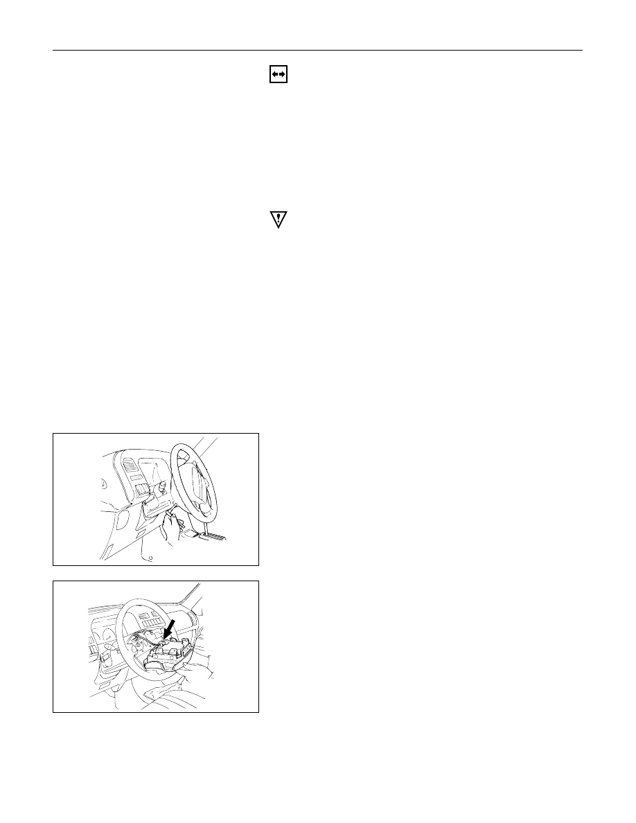
5. Inflator Module

1) Loosen the inflator module fixing bolt from

behind the steering wheel assembly using a
TORX

driver or equivalent until the inflator

module can be released from steering assembly.

2) Disconnect the yellow 2way SRS connector

located behind the inflator module.

827RS014

827RS015

SUPPLEMENTAL RESTRAINT SYSTEM STEERING WHEEL & COLUMN  2A – 71

WARNING
THE INFLATOR MODULE SHOULD ALWAYS BE CARRIED
WITH THE URETHANE COVER AWAY FROM YOUR BODY
AND SHOULD ALWAYS BE LAID ON A FLAT SURFACE
WITH THE URETHANE SIDE UP.  THIS IS NECESSARY
BECAUSE A FREE SPACE IS PROVIDED TO ALLOW THE
AIR CUSHION TO EXPAND IN THE UNLIKELY EVENT OF A
ACCIDENTAL DEPLOYMENT.  OTHERWISE, PERSONAL
INJURY MAY RESULT.

6. Steering Wheel

Apply a setting mark across the steering wheel and
shaft so parts can be reassembled in their original
position.

Use special tool.  Remove the steering wheel.
Move the tires to the straight ahead position before
removing the steering wheel.

Steering wheel remover:  5-8840-0016-0 (J-29752)

7. Steering Column Cover

8. Combination Switch and SRS Coil Assembly

1) Disconnect the wiring harness connectors

located under the steering column.

2) Remove the combination switch assembly with

SRS coil.

NOTE:
The SRS coil is a part of the combination switch
assembly, which can not be replaced separately.
Therefore, be sure not to remove the SRS coil from
the combination switch assembly.

9. Snap Ring

10. Cushion Rubber

11. Shift Lock Cable (for A/T)

12. Lock Cylinder Assembly

Disconnect the starter switch harness connector
located under the steering column.

827RS016

825RS046

Up

430RS004

Setting mark

2A – 72 SUPPLEMENTAL RESTRAINT SYSTEM STEERING WHEEL & COLUMN

Setting mark

13. Steering Column Assembly

Apply a setting mark across the universal joint and
steering shaft to reassemble the parts in their original
position.

NOTE:
A setting mark can be easily made if the shaft is
withdrawn a little by loosening the steering shaft
universal joint.

431RV003

INSTALLATION

13. Steering Column Assembly

Align the setting marks on the universal joint and
steering shaft made during removal.

Tighten the steering column fixing bolt (dash panel)
to the specified torque.

Steering Column Bolt Torque

N·m (kg·m/lb·ft)

19 (1.9 / 14)

Tighten the steering column fixing bolt (pedal
bracket) to the specified torque.

Steering Column Bolt Torque

N·m (kg·m/lb·ft)

17 (1.7 / 13)

Tighten the universal joint to the specified torque.

Universal Joint Torque

N·m (kg·m/lb·ft)

25 (2.5 / 18)

12. Lock Cylinder Assembly

11. Shift Lock Cable (for A/T)

10. Cushion Rubber

9. Snap Ring

8. Combination Switch

1)

After installation of combination switch
assembly, connect the combination switch
wiring harness connector and the SRS 2way
connector located under the steering column.

2)

Turn the SRS coil counterclockwise to full, return
about 3 turns and align the neutral mark.

CAUTION:
When turning the SRS coil counterclockwise to full, stop
turning if resistance is felt.  Forced further turning may
damage to the cable in the SRS coil.

Alignment mark

826RW027

SUPPLEMENTAL RESTRAINT SYSTEM STEERING WHEEL & COLUMN  2A – 73

Starter switch 
harness
Combination
switch harness
Inflator module
 harness

Setting cowl
(Lower)

7. Steering Column Cover

When installing the steering column cover, be sure to
route each wire harness as illustrated so that the
harnesses do not catch on any moving parts.

6. Steering Wheel

Align the setting marks made when removing.

CAUTION:
Never apply force to the steering wheel in direction of the
shaft by using a hammer or other impact tools in an
attempt to remove the steering wheel.  The steering shaft
if designed as an energy absorbing unit.

Tighten the steering wheel fixing nut to the specified
torque.

Steering Wheel Nut Torque

N·m (kg·m/lb·ft)

34 (3.5 / 25)

5. Inflator Module

1) Support the module and carefully connect the

module connector.

CAUTION:

Never use the air bag assembly from another vehicle.
Use only the air bag assembly for "UBS".

When replace the inflator module, use only same parts
number assembly. If different parts number assembly is
installed, the air bag system can not function correctly
because it has different characteristic.

NOTE:
Pass the lead wire through the tabs on the plastic
cover (wire protector) of inflator to prevent lead wire
from being pinched.

2) Secure the module with one bolt to relieve

weight on the connector wire.

3) Tighten bolts to specified sequence as figure.

Inflator Module Bolt Torque

N·m (kg·m/lb·in)

8 (0.8 / 69)

4

Driver Knee Bolster (Reinforcement)

3. Steering Lower Cover

Install the engine hood opening lever.

2. Lower Cluster Assembly

1. Front Console Assembly

Connect the wiring harness connectors.
Install the transmission (for M/T) and transfer control
lever knob.

Connect the yellow 2way SRS connector located
under the steering column.

Connect the battery ground cable.

825RS048

3

4

1

2

827RS017


Content   ..  961  962  963  964   ..