Opel Frontera UBS. Manual - part 959


  Index      Opel     Opel Frontera UBS - service repair manual 1998-2002 year


Search            


Content   ..  957  958  959  960   ..


Opel Frontera UBS. Manual - part 959


2A – 54 SUPPLEMENTAL RESTRAINT SYSTEM STEERING WHEEL & COLUMN

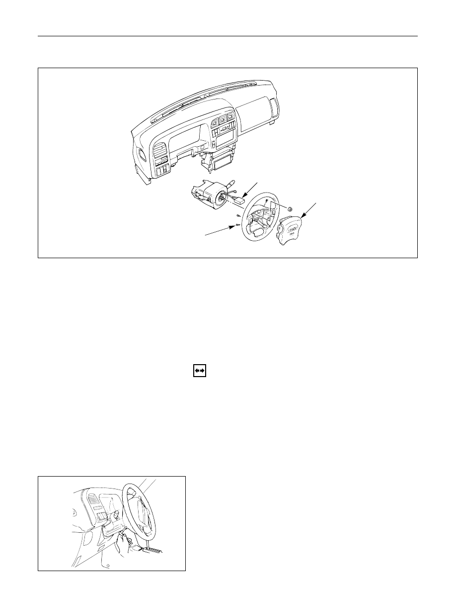
INFLATOR MODULE REPLACEMENT

1

3

2

Removal Steps

1. Fixing bolt
2. Module connector
3. Inflator module

Installation Steps

3. Inflator module
2. Module connector
1. Fixing bolt

827RS049

These steps are based on the LHD model.

REMOVAL

Preparation:

1) Turn the steering wheel so that the vehicle's wheels

are pointing straight ahead.

2) Turn the ignition switch to "LOCK".

3) Disconnect the battery ground cable, and wait at least

5 minutes.

4) Disconnect the yellow 2way SRS connector located

under the steering column.

1. Fixing Bolt

Loosen the inflator module fixing bolt from behind
the steering wheel assembly using a TORX‚ driver or
equivalent until the inflator module can be released
from steering assembly.

827RS014

SUPPLEMENTAL RESTRAINT SYSTEM STEERING WHEEL & COLUMN  2A – 55

2. Module Connector

Disconnect the yellow 2way SRS connector located
behind the inflator module.

3. Inflator Module

827RS015

827RS016

INSPECTION AND REPAIR

WARNING
THE INFLATOR MODULE SHOULD ALWAYS BE CARRIED
WITH THE URETHANE COVER AWAY FROM YOUR BODY
AND SHOULD ALWAYS BE LAID ON A FLAT SURFACE
WITH THE URETHANE SIDE UP.  THIS IS NECESSARY
BECAUSE A FREE SPACE IS PROVIDED TO ALLOW THE
AIR CUSHION TO EXPAND IN THE UNLIKELY EVENT OF
ACCIDENTAL DEPLOYMENT.  OTHERWISE, PERSONAL
INJURY MAY BE RESULT.

INSTALLATION

3. Inflator Module

CAUTION:

Never use the air bag assembly from another vehicle.
Use only the air bag assembly for "UBS".

When replace the inflator module, use only same parts
number assembly. If different parts number assembly is
installed, the air bag system can not function correctly
because it has different characteristic.

2. Module Connector

Support the module and carefully connect the
module connector.

NOTE:
Pass the lead wire through the tabs on the plastic
cover (wire protector) of inflator to prevent lead wire
from being pinched.

The Inflator module consists of a cover, air bag,
inflator, and retainer.  Inspect the Inflator module
mainly for the following:

1) Check for holes, cracks, severe blemishes and

deformation on the cover.

2) Check that the retainer is not deformed.

3) Check for defects such as damage and breakage

in the lead wire of the squib.

If an abnormality is found as the result of the
inspection, replace the Inflator module with a new
one.

Up

2A – 56 SUPPLEMENTAL RESTRAINT SYSTEM STEERING WHEEL & COLUMN

3

4

1

2

1. Fixing Bolt

1) Secure the module with one bolt to relieve

weight on the connector wire.

2) Tighten bolts to specified sequence as figure.

N·m (kg·m/lb·in)

8 (0.8 / 69)

3) Connect the yellow 2way SRS connector located

under the steering column.

4) Connect the battery ground cable.

5) Set ignition to "ON" while watching warning

light.  Light should flash 7 times and then go off.
If lamp does not operate correctly, refer to
Section 9J.

827RS017

SUPPLEMENTAL RESTRAINT SYSTEM STEERING WHEEL & COLUMN  2A – 57

STEERING WHEEL REPLACEMENT

1

3

2

4

Removal Steps

1. Inflator module
2. Horn lead
3. Steering wheel fixing nut
4. Steering wheel

Installation Steps

4. Steering wheel
3. Steering wheel fixing nut
2. Horn lead
1. Inflator module

430RS016

These steps are based on the LHD model.

REMOVAL

Preparation:

1) Turn the steering wheel so that the vehicle's wheels

are pointing straight ahead.

2) Turn the ignition switch to "LOCK".

3) Disconnect the battery ground cable, and wait at least

5 minutes.

4) Disconnect the yellow 2way SRS connector located

under the steering column.

CAUTION:
Once the steering column is removed from the vehicle, the column is extremely suspectible to
damage.  Dropping the column assembly on its end could collapse the steering shaft or loosen the
slide block which maintains column rigidity.  Leaning on the column assembly could cause the jacket
to bend or deform.  Any of the above damage could impair the column's collapsible design.  If it is
necessary to remove the steering wheel, use only the specified steering wheel puller.  Under no
conditions should the end of the shaft be hammered upon, as hammering could loosen slide block
which maintains column rigidity.


Content   ..  957  958  959  960   ..