Opel Frontera UBS. Manual - part 957


  Index      Opel     Opel Frontera UBS - service repair manual 1998-2002 year


Search            


Content   ..  955  956  957  958   ..


Opel Frontera UBS. Manual - part 957


2A – 46 STEERING LINKAGE

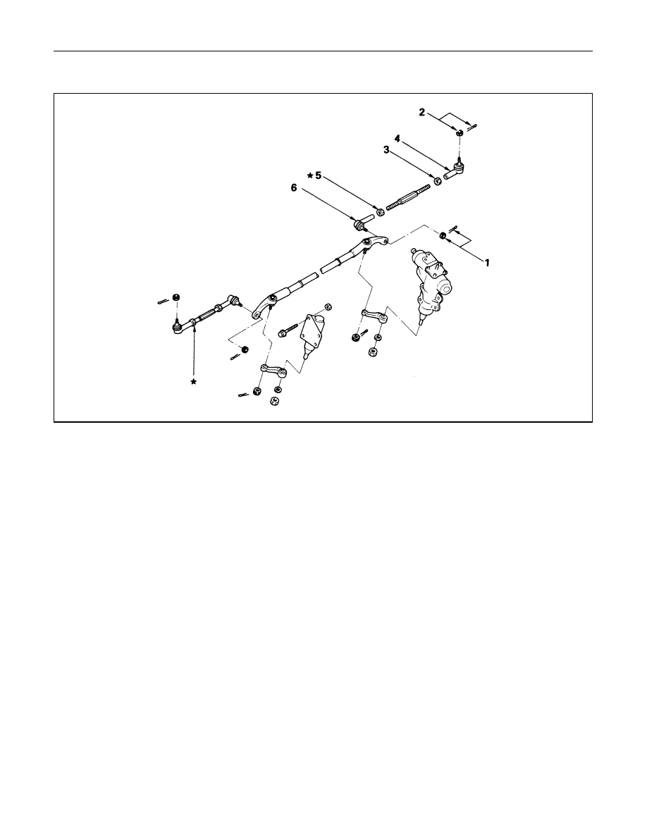
OUTER TRACK ROD ASSEMBLY

Removal Steps

1.

Nut and cotter pin, center track rod

2.

Nut and cotter pin, knuckle arm

3.

Lock nut, outer

4.

Rod end assembly outer

5.

Lock nut, inner

6.

Rod end assembly, inner

★ The screw is threaded 

counterclockwise.

Installation Steps

6.

Rod end assembly, inner

5.

Lock nut, inner

4.

Rod end assembly outer

3.

Lock nut, outer

2.

Nut and cotter pin, knuckle arm

1.

Nut and cotter pin, center track 
rod

These steps are based on the LHD model.

STEERING LINKAGE  2A – 47

REMOVAL

Preparation:
Remove wheel and tire assembly.
Refer to “Wheels and Tires” in section 3E.

1. Nut and Cotter Pin, Center Track Rod

Disconnect outer track rod assembly at the center
track rod.

Remover: 5-8840-2121-0 (J-36831)

CAUTION:
Be careful not to break the ball joint boot.

2. Nut and Cotter Pin, Knuckle Arm

Remove outer track rod assembly from the knuckle
arm.

Remover: 5-8840-2121-0 (J-36831)

CAUTION:
Be careful not to break the ball joint boot.

3. Lock Nut, Outer

NOTE:
In either outer rod, the screw on the right side of the
vehicle is threaded counterclockwise.

6. Rod End, Inner

Apply setting marks to ensure reassembly of the
parts in their original position.

4. Rod End Assembly, Outer

Apply setting marks to ensure reassembly of the
parts in their original position.

5. Lock Nut, Inner

NOTE:
In either outer rod, the screw on the right side of the
vehicle is threaded counterclockwise.

2A – 48 STEERING LINKAGE

INSPECTION AND REPAIR

Make necessary correction or parts replacement if wear,
damage, corrosion, bending, deteriorations or any other
abnormal condition are found through inspection.
Check the following parts.

Rod end assembly

Ball joint (Boot, screws and tapered surfaces)

INSTALLATION

6. Rod End, Inner

Align the setting marks applied during desassembly.

5. Lock Nut, Inner

Lock Nut Torque 

N·m (kg·m/lb·ft)

118 (12.0 / 87)

NOTE:
In either outer rod, the screw on the right side of the
vehicle is threaded counterclockwise.

4. Rod End Assembly, Outer

Align the setting marks applied during disassembly.

3

Lock Nut, Outer

Lock Nut Torque

N·m (kg·m/lb·ft)

118 (12.0 / 87)

2. Nut and Cotter pin, Knuckle Arm

Tighten the nut to the specified torque, with just
enough additional torque to align cotter pin holes.
Install new cotter pin.

Knuckle Arm Nut Torque

N·m (kg·m/lb·ft)

98 (10.0 / 72)

1. Nut and Cotter Pin, Center Track Rod

Tighten the nut to the specified torque, with just
enough additional torque to align cotter pin holes.
Install new cotter pin.

Track Rod Nut Torque

N·m (kg·m/lb·ft)

98 (10.0 / 72)

NOTE:
If replacing the track rod, adjust the new track rod
length.

Rod Length (L)

mm (in)

328.3 (12.93) : Wide Tread

299 (11.77) : Narrow Tread

NOTE:
Adjust the toe-in. Refer to “Front End Alignment” in
section 3A.

STEERING LINKAGE  2A – 49

RELAY LEVER

2

2

3

6

5

4

1

hese steps are based on the LHD model.

Removal Steps

1.

Nut and cotter pin

2.

Bolt and nut

3.

Relay lever and Bracket

4.

Nut and washer

5.

Relay lever

6.

Bracket

Installation Steps

6.

Bracket

5.

Relay lever

4.

Nut and washer

3.

Relay lever and bracket

2.

Bolt and nut

1.

Nut and cotter pin

REMOVAL

Preparation:
Raise the vehicle and support the frame with suitable
safety stands.

1. Nut and Cotter pin

Disconnect relay lever at the center track rod.

Remover: 5-8840-2121-0 (J-36831)

433RW005

These steps are based on the LHD model.


Content   ..  955  956  957  958   ..