Opel Frontera UBS. Manual - part 901
1A – 30 HEATING AND VENTILATION
4
4a
3
Full hot switch
Cover
Clamp
2
20
25
30
AUT
O
A/C
OF
F
AUTO
LO
HI
1
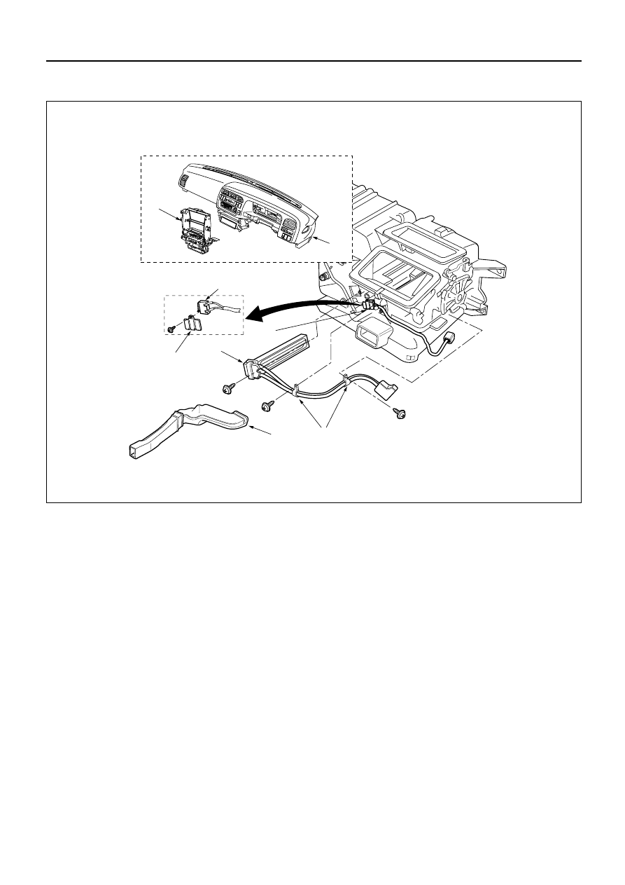
Removal Steps
1. Instrument panel assembly
2. Instrument panel center bracket
3. Rear heater duct
4. Ceramic heater assembly
4a. Full hot switch
CERAMIC HEATER AND/OR FULL HOT SWITCH
Installation Steps
To install, follow the removal steps in
the reverse order.
This illustration is based on RHD