Opel Frontera UBS. Manual - part 899


  Index      Opel     Opel Frontera UBS - service repair manual 1998-2002 year


Search            


Content   ..  897  898  899  900   ..


Opel Frontera UBS. Manual - part 899


1A – 22 HEATING AND VENTILATION
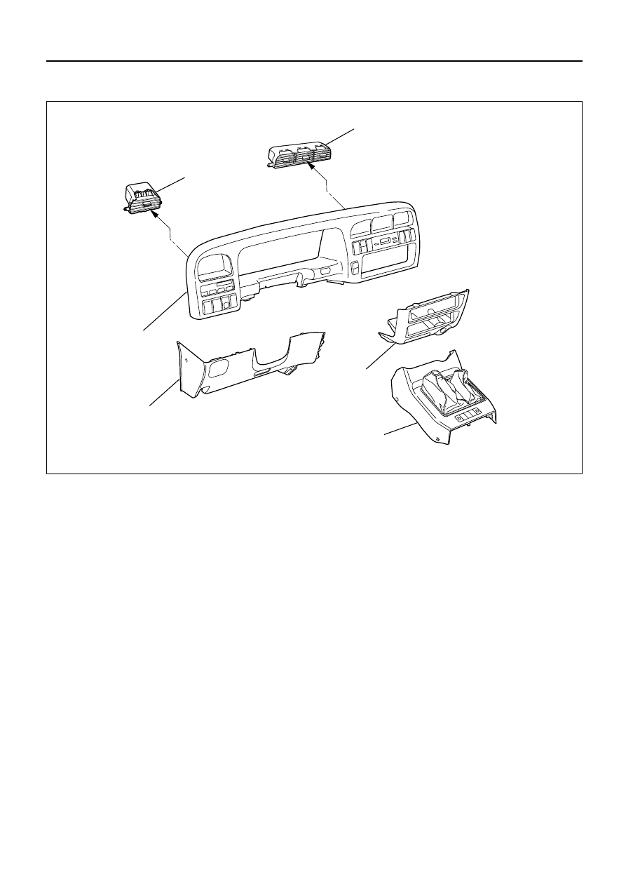
Removal Steps

1. Front console assembly
2. Lower cluster assembly
3. Instrument panel driver lower

cover assembly

4. Meter cluster assembly
5. Center vent
6. Side vent

Installation Steps

To install, follow the removal steps in the
reverse order.

CENTER AND/OR SIDE VENT

6

5

3

1

2

4

This illustration is based on LHD

740RW168

HEATING AND VENTILATION  1A – 23

INSTALLATION

To install, follow the removal steps in the reverse order.

REMOVAL

1. Front console assembly

2. Lower cluster assembly

3. Instrument panel driver lower cover assembly

4. Meter cluster assembly

Refer to Section 10 “BODY” for INSTRUMENT
PANEL ASSEMBLY removal procedure.

5. Center vent

Remove screws and the center vent from center
cluster while prying up the center vent catch
portions.

6. Side vent

Remove screws and the side vent from center
cluster while prying up the side vent catch
portions.

1A – 24 HEATING AND VENTILATION

Removal Steps

1. Center console assembly
2. Lower cluster assembly
3. Glove box
4. Instrument panel passenger lower

cover assembly

5. Instrument panel driver lower cover

assembly

6. Meter cluster assembly
7. Attaching screws
8. Fan switch and air conditioning switch

connector

9. Control lever assembly

10. Control cable

CONTROL LEVER ASSEMBLY AND/OR CONTROL CABLES

1

5

2

10

7

7

8

8

9

10

To Mode control link

To Temp control link

To Blower assembly

4

3

Installation Steps

To install, follow the removal steps in
the reverse order.

This illustration is based on LHD

HEATING AND VENTILATION  1A – 25

REMOVAL

Preparation:

Disconnect the battery ground cable 

1. Front console assembly 

2. Lower cluster assembly

3. Glove box

4. Instrument panel passenger lower cover

5. Instrument panel driver lower cover

6. Meter cluster assembly

Refer to Section 10 “BODY” for INSTRUMENT PANEL
ASSEMBLY removal procedure. 

7. Attaching Screws

Remove the 4 attaching screws and disconnect the
control lever cables at heater unit and blower
assembly.

8. Fan Switch and A/C Switch Connector

Pull the control lever assembly out and disconnect
the connectors.

9. Control Lever Assembly 

10. Control Cable 


Content   ..  897  898  899  900   ..