Opel Frontera UBS. Manual - part 897


  Index      Opel     Opel Frontera UBS - service repair manual 1998-2002 year


Search            


Content   ..  895  896  897  898   ..


Opel Frontera UBS. Manual - part 897


1A – 14 HEATING AND VENTILATION
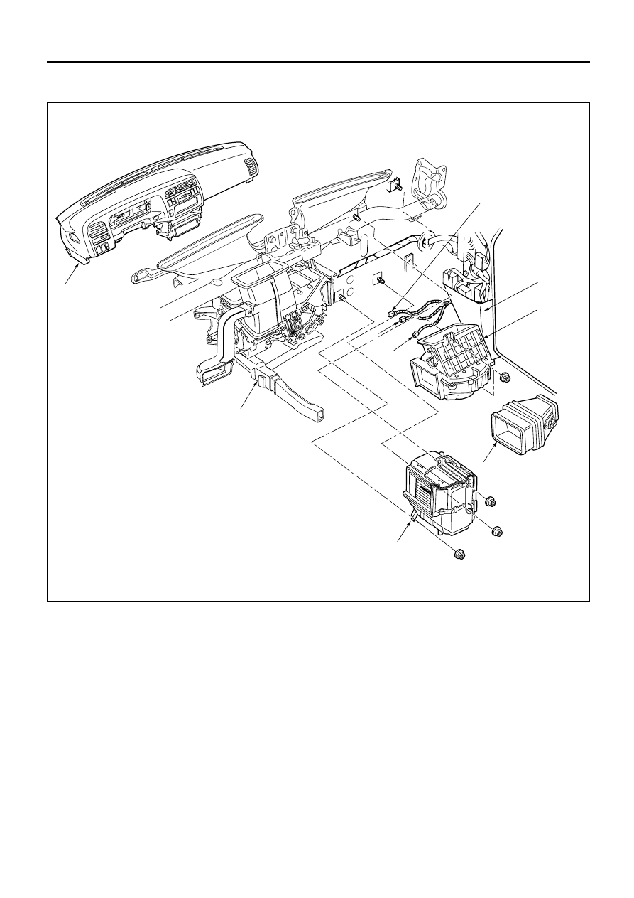
Removal Steps

1. Instrument panel assembly
2. Resistor connector
3. Duct
3a. Evaporator assembly (A/C only)
4. Kick panel
5. Blower motor connector
6. Blower assembly

Installation Steps

To install, follow the removal steps in the
reverse order.

BLOWER ASSEMBLY

2

3a(With A/C)

3

Heater unit

Electro thermo connector
 (With A/C)

1

4

6

5

This illustration is based on LHD

HEATING AND VENTILATION  1A – 15

REMOVAL

Preparation:

Disconnect the battery ground cable

Discharge and recover refrigerant (W/A/C)
(Refer to Section 1B “REFRIGERANT RECOVERY”) 

1. Instrument Panel Assembly

Refer to Section 10 “BODY” for INSTRUMENT PANEL
ASSEMBLY removal procedure. 

2. Resistor Connector 

3. Duct 

3a. Evaporator Assembly (A/C only)

Refer to Section 1B “AIR CONDITIONING” for
EVAPORATOR ASSEMBLY removal procedure. 

4. Kick panel 

5. Blower Motor Connector 

6. Blower Assembly

INSTALLATION

To install, follow the removal steps in the reverse order,
noting the following point: 

1. Adjust Control Lever Assembly Cables

Refer to “CONTROL LEVER ASSEMBLY” installation
procedure in this section.

1A – 16 HEATING AND VENTILATION

Removal Steps

1. Blower assembly
2. Lower case
3. Upper case
4. Mode door
5. Sub-lever
6. Door lever

Installation Steps

To install, follow the removal steps in the
reverse order.

BLOWER LINK UNIT AND/OR MODE DOOR

This illustration is based on LHD

1

3

6

2

4

5

HEATING AND VENTILATION  1A – 17

REMOVAL

Preparation:

Disconnect the battery ground cable 

1. Blower Assembly

Refer to “BLOWER ASSEMBLY” removal procedure
in this section. 

2. Lower Case 

3. Upper Case

Separate upper case and slit the lining parting face
with a knife.

INSTALLATION

To install, follow the removal steps in the reverse order,
noting the following points: 

1. Apply grease to the door lever and to the abrasive

surface of the upper case.

2. Apply an adhesive to parting face of lining when

assembling upper case.


Content   ..  895  896  897  898   ..