Opel Frontera UBS. Manual - part 833
8H–16 SECURITY AND LOCKS
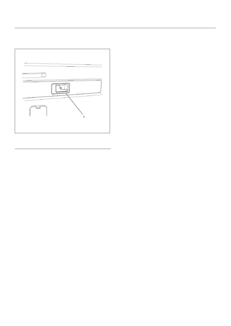
Tailgate Inside Handle
Parts Location
683RW013
Legend
(1) Tailgate Inside Handle
Removal and Installation
D
Refer to the Tailgate Trim Panel (LH) removal
procedure in Exterior/Interior Trim section.