Content .. 2905 2906 2907 2908 ..
Opel Frontera UBS. Manual - part 2907
EXTERIOR/INTERIOR TRIM
8J–39
Power Window System
General Description
The circuit consists of the starter switch, (door lock &)
power window switch for each of the front windows,
power window switch for rear windows and power window
motors.
When the starter switch is turned on, the battery voltage is
applied to each of the power window switches through the
circuit breaker and the power window relay on the circuit.
The “Down” switch of the driver’s power window switch
has a built-in function which can be operated by just
touching it.
Accordingly, the window will roll down automatically by
just setting the switch to the “AUTO” position.
When the driver’s power lock switch at the driver side is
depressed, the power source to the passenger’s power
window switches are shut off. So, even if these switches
are operated, the power window motor will not operate.
Power Window Switch Removal and
Installation
Driver Seat Side
Removal
1. Disconnect the battery ground cable.
2. Remove the switch(1).
D
Pull out the switch by pushing the spring with the tip
of a screwdriver.
D
Disconnect two connectors.
825RS052
Installation
To install, follow the removal steps in the reverse order.
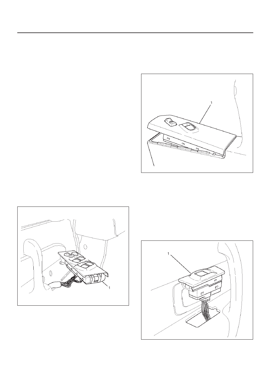
Front Passenger Seat Side
Removal
1. Disconnect the battery ground cable.
2. Remove the switch(1).
D
Pull out the switch by pushing the spring with the tip
of a screwdriver.
D
Disconnect the connector.
825RW046
Installation
To install, follow the removal steps in the reverse order.
Rear-Left and Right Sides
Removal
1. Disconnect the battery ground cable.
2. Remove the switch(1).
D
Pull out the switch by pushing the spring with the tip
of a screwdriver.
D
Disconnect the connector.
825RS057
Installation
To install, follow the removal steps in the reverse order.