Opel Frontera UBS. Manual - part 2906


  Index      Opel     Opel Frontera UBS - service repair manual 1998-2002 year


Search            


Content   ..  2904  2905  2906  2907   ..


Opel Frontera UBS. Manual - part 2906


EXTERIOR/INTERIOR TRIM

8J–35

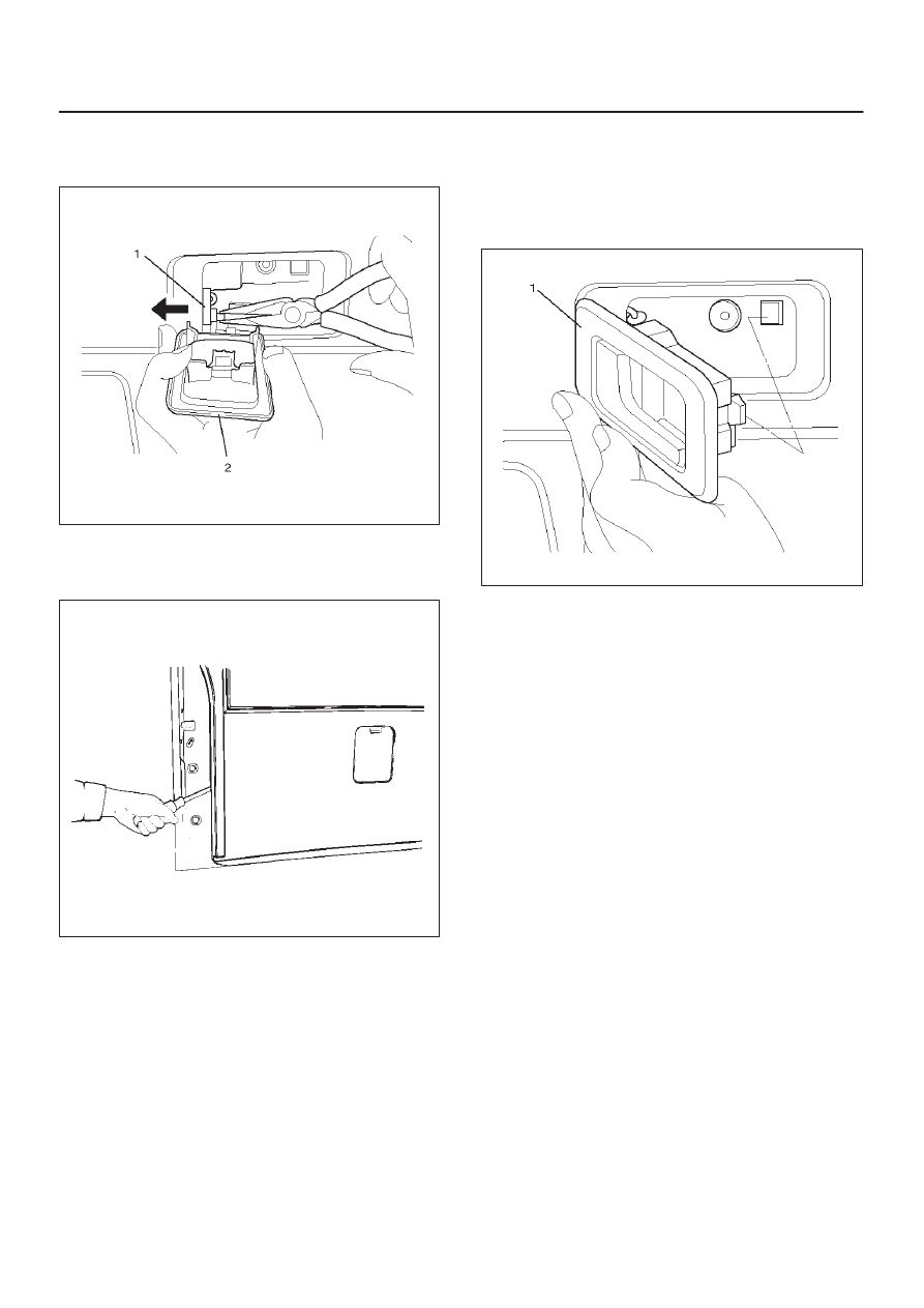
3. Remove the inside handle (2).

D

Remove the fixing screw and disconnect the locking
link (1).

683RW020

4. Remove the tailgate trim panel (LH).

D

Pry the trim panel retainers free from the tailgate
panel.

684RS001

Installation

To install, follow the removal steps in the reverse order,
noting the following point.

1. Install the inside handle (1), connect the link to the

handle, insert the catch portion of the handle into the
tailgate side hole securely and fix it with a screw.

683RW018

8J–36

EXTERIOR/INTERIOR TRIM

Tailgate Trim Panel (RH)

Parts Location

684RS002

Legend

(1) Tailgate Trim Panel

Removal

1. Disconnect the battery ground cable.
2. Remove the tailgate trim panel (RH).

D

Pry trim panel retainer free from the tailgate panel.

684RS003

Installation

To install, follow the removal steps in the reverse order,
noting the following points.

1. Insert the retainer of the trim panel into the tailgate

panel and fix it securely.

EXTERIOR/INTERIOR TRIM

8J–37

Luggage Floor Box

Luggage Floor Box and Associated
Parts

643RS006

Legend

(1) Rear Seat
(2) Floor Carpet
(3) Luggage Floor Box
(4) Luggage Floor Box Cover

Remove

1. Fold the rear seat assembly to the front direction.
2. Remove the luggage floor box cover.

D

Remove the clips which connect the floor carpet
and the luggage floor box cover.

3. Remove the luggage floor box.

Installation

To install, follow the removal steps in the reverse order.

Rope Hook Set

Rope Hook Set and Associated Parts

676RS003

Legend

(1) Rope Hook Set
(2) Cover
(3) Luggage Floor Carpet
(4) Hook

Removal

1. Remove the rope hook set.

D

Open the hook cover and hook fixing bolt.

Installation

1. Install the rope hook set.

D

Tighten the hook fixing bolt to the specified torque.

Torque: 13 N·m (1.3kg·m/113 lb in)

8J–38

EXTERIOR/INTERIOR TRIM

Power Door Mirror System

General Description

The circuit consists of the starter switch, door mirror
control switch, folding switch, defogger switch and door
mirrors on both sides.
The door mirror switch consists of the control switch,
folding switch and defogger switch.
When the control switch is operated with the starter
switch at either “ACC” or “ON” position, the motors
incorporated in the door mirrors on both sides rotates to
allow the horizontal and vertical adjustment of mirror
angles.
The folding switch can be used to fold the mirror and
return it to its original position.
When turning on the door mirror defogger switch with the
starter switch at “ON” position, built-in heater in the mirror
is activated to perform the defogger function.

Door Mirror Switch Assembly
(Control Switch, Folding Switch and
Defogger Switch) Removal

1. Disconnect the battery ground cable.
2. Remove the front console assembly(2).

D

Remove four screws.

D

Remove the transmission shift lever knob.

D

Remove the transfer shift lever knob.

D

Disconnect the seat heater switch connectors (if so
equipped).

D

Disconnect the door mirror switch connectors.

D

Disconnect the power & winter switch connectors.
(A/T only)

3. Remove the door mirror switch assembly(1).

D

Push the lock from the back side of the front
console.

825RS005

Installation

To install, follow the removal steps in the reverse order,
noting the following point.

1. Depress the switch with your fingers until it locks

securely.

Power Door Mirror

General Description

Mirrors contain two driving motors for the horizontal and
vertical movement of the mirror and one motor for folding
the mirror.
The movement of the mirror is controlled by the direction
of current running through these motors.
The housing portion of the mirror is provided with the
auto-stop mechanism which is interlocked with the motor
for folding the mirror.  When the mirror moves to the stop
position (with the mirror folded or returned to its original
position), the current to the motor is shut off.
When the mirror cannot operate due to some obstacle
and the motor stops its rotation, the resistor prevents
current overflow.

720RS004

Removal and Installation

Refer to the Door Mirror removal and installation steps in
this section.


Content   ..  2904  2905  2906  2907   ..