Opel Frontera UBS. Manual - part 2690


  Index      Opel     Opel Frontera UBS - service repair manual 1998-2002 year


Search            


Content   ..  2688  2689  2690  2691   ..


Opel Frontera UBS. Manual - part 2690


8A–14

LIGHTING SYSTEM

Map Light Switch/Bulb

Removal

1. Disconnect the battery ground cable.
2. Pull the map light body downward to release the lock.
3. Disconnect the connectors of the map light and the

sun roof switch.

4. Remove the map light switch.
5. Turn the socket counterclockwise to remove it.
6. Pull out the bulb from the socket.

805RS008

Installation

To install, follow the removal steps in the reverse order.

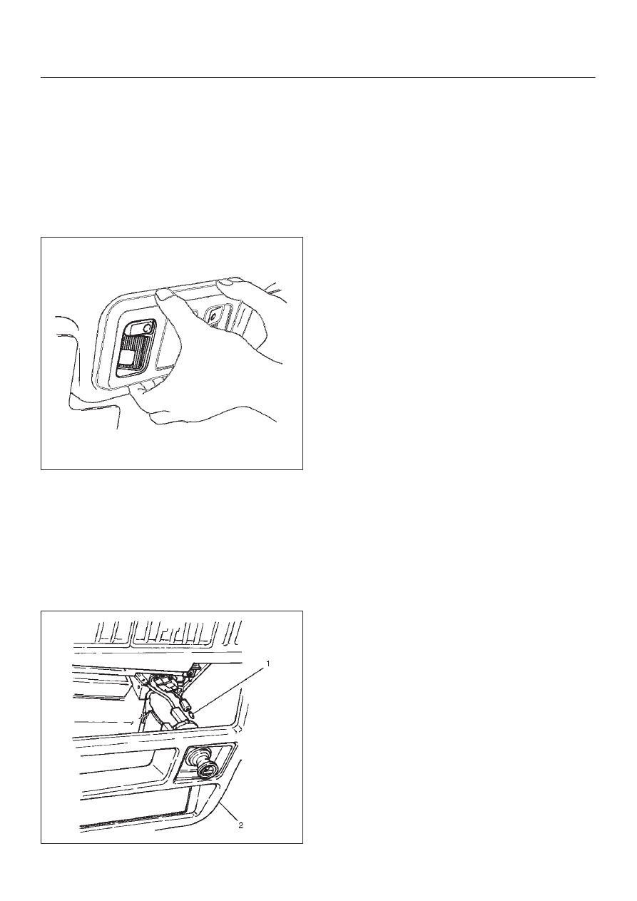
Cigarette Lighter Illumination Bulb

Removal

1. Disconnect the battery ground cable. 
2. Remove eight screws to remove the instrument

cluster panel(2). 

3. Turn the socket counterclockwise to remove it then

pull out the bulb(1). 

826RS013

Installation 

To install, follow the removal steps in the reverse order.

LIGHTING SYSTEM

8A–15

Ashtray Illumination Bulb

Removal

1. Disconnect the battery ground cable. 
2. Removal eight screws to remove the instrument

cluster panel(1). 

3. Remove the ashtray(5). 
4. Remove four screws to remove the audio box(4). 
5. Remove two screws to remove the ashtray guide(2). 
6. Turn the socket counterclockwise to remove it then

pull out the bulb(3). 

742RS001

Installation

To install, follow the removal steps in the reverse order.

Glove Box Illumination Bulb

Removal

1. Disconnect the battery ground cable.
2. Open the glove box lid, and then pull out the bulb(1).

805RS004

Installation

To install, follow the removal steps in the reverse order.

8A–16

LIGHTING SYSTEM

Vanity Mirror Illumination Bulb

Removal

1. Disconnect the battery ground cable.
2. Remove the lens(2).
3. Remove the bulb(1).

743RW007

Installation 

To install, follow the removal steps in the reverse order.

LIGHTING SYSTEM

8A–17

Starter Switch

Removal

1. Disconnect the battery ground cable.
2. Remove the front console assembly(1).

Refer to Instrument Panel Assembly in Body
Structure section.

3. Remove the lower cluster assembly(2).

Refer to the Instrument Panel Assembly in Body
Structure section.

4. Remove the instrument panel driver lower cover

assembly(3).
Refer to the Instrument Panel Assembly in Body
Structure section.

821RW024

5. Remove seven screws to remove the steering

cowl(6).

6. Disconnect the connector, remove the screw(4) and

then remove the starter switch(5).

431RW005

Installation

 To install, follow the removal steps in the reverse order
noting the following point.

1. When installing the steering cowl(10), be sure to pass

the harnesses through the route as shown in the
figure so that the starter switch harness(7), the
combination switch harness(8) and the inflator
module harness(9) will not get caught. 

431RW008


Content   ..  2688  2689  2690  2691   ..