Opel Frontera UBS. Manual - part 2642


  Index      Opel     Opel Frontera UBS - service repair manual 1998-2002 year


Search            


Content   ..  2640  2641  2642  2643   ..


Opel Frontera UBS. Manual - part 2642


7B–44 MANUAL TRANSMISSION

226RW096

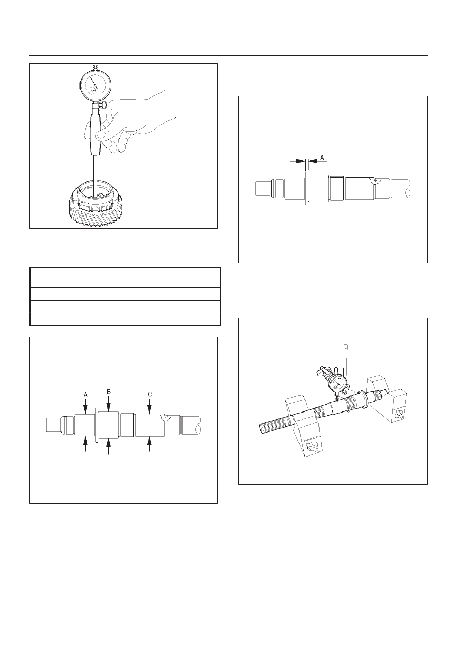
7. Inspect mainshaft.

1. Using a micrometer, measure the outer diameter

of the mainshaft journal.

Measure

Position

Standard

A

37.984 – 38.000 mm (1.4954 – 1.4961 in)

B

46.984 – 47.000 mm (1.8498 – 1.8504 in)

C

38.979 – 38.995 mm (1.5346 – 1.5352 in)

226RW078

2. Using a micrometer, measure the mainshaft

flange thickness.

Standard: 5.0 mm (0.197 in)

226RW079

3. Install the mainshaft to V-blocks.

4. Use a dial indicator to measure the mainshaft

central portion run-out.

Standard: less than 0.015 mm (0.0006 in)

226RW097

MANUAL TRANSMISSION

7B–45

8. Install 3rd gear.

1. Install the 3rd gear needle bearing, 3rd gear and

3rd block ring to the mainshaft.

226RW098

9. Install the clutch hub No.2.

1. Install the clutch hub No.2 and hub sleeve No.2.

NOTE: Be careful the direction of the clutch hub No.2, as
shown.

2. Using a screwdriver, install 3 inserts and 2

springs.

NOTE: Position the insert springs so that their end gaps
are not in line.

226RW099

3. Using installer 5–8840–2553–0 (J–42797) and a

press, install the clutch nob No.2 and hub sleeve
No.2 to the mainshaft.

NOTE:

D

Align the brock ring slots with the inserts.

D

Check that the gear rotates smoothly.

226RW206

4. Select a snap ring that will allow minimum axial

play.

Mark

Thickness

A

1.80 – 1.85 mm (0.071 – 0.073 in)

B

1.85 – 1.90 mm (0.073 – 0.075 in)

C

1.90 – 1.95 mm (0.075 – 0.077 in)

D

1.95 – 2.00 mm (0.077 – 0.079 in)

E

2.00 – 2.05 mm (0.079 – 0.081 in)

F

2.05 – 2.10 mm (0.081 – 0.083 in)

G

2.10 – 2.15 mm (0.083 – 0.085 in)

226RW102

7B–46 MANUAL TRANSMISSION

5. Using a snap ring expander, install the new snap

ring.

NOTE: Be careful not to damage the bearing surface.

226RW101

6. Using a thickness gauge, inspect the 3rd gear

thrust clearance.

Standard: 0.10 – 0.25mm (0.004 – 0.010 in)

226RW103

10. Install the 2nd gear.

1. Install the synchronizer ring set No.1 to the 2nd

gear.

NOTE: Align the nail of middle ring with gear spline slots.

226RW104

2. Install the needle roller bearing, 2nd gear and 2nd

gear block ring set to the mainshaft.

226RW107

MANUAL TRANSMISSION

7B–47

11. Install the clutch hub No.1.

1. Install the 3 inserts and 3 insert springs to the

clutch hub No.1.
Reference:  While pushing the insert spring
with a screwdriver, install the inserts.

226RW108

2. Install the clutch hub No.1 to the reverse gear.

NOTE: Check the clutch hub No.1 installing direction, as
shown.

226RW109

3. Using installer 5–8840–2554–0 (J–42798) and a

press, install the hub No.1 by retaining the
reverse gear.

NOTE:

D

Align the projection of inner ring with hub No.1 slots.

D

Check that the gear rotates smoothly.

226RW205

4. Select a snap ring that will allow minimum axial

play.

Mark

Thickness

A

2.30 – 2.35 mm (0.091 – 0.093 in)

B

2.35 – 2.40 mm (0.093 – 0.095 in)

C

2.40 – 2.45 mm (0.095 – 0.097 in)

D

2.45 – 2.50 mm (0.097 – 0.098 in)

E

2.50 – 2.55 mm (0.098 – 0.100 in)

F

2.55 – 2.60 mm (0.100 – 0.102 in)

G

2.60 – 2.65 mm (0.102 – 0.104 in)

226RW111


Content   ..  2640  2641  2642  2643   ..