Content .. 2630 2631 2632 2633 ..
Opel Frontera UBS. Manual - part 2632
7B–4
MANUAL TRANSMISSION
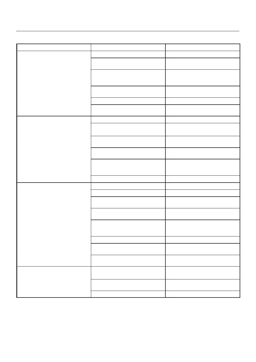
Diagnosis
Condition
Possible cause
Correction
Abnormal noise
Flywheel pilot bearing worn
Replace
Bearings worn or broken (Mainshaft,
counter shaft, and transfer shaft)
Replace
Gear tooth contact surfaces worn or
scuffed (Mainshaft, counter shaft,
reverse idler gear and transfer gears)
Replace
Splines worn (Mainshaft,
synchronizer clutch hub)
Replace
Gear or bearing thrust face seized
Replace
Lack of backlash between meshing
gears
Replace
Hard Shifting
Improper clutch pedal free play
Readjust
Change lever sliding portions worn
Repair or replace
Regrease
Shift block, shift rod and/or control
box sliding faces worn
Replace
Shift arm and synchronizer sleeve
groove worn
Replace worn parts
Thrust washer, collar, and/or gear
thrust faces worn (Mainshaft and
counter shaft thrust play)
Replace worn parts
Synchronizer parts worn
Replace
Walking or Jumping out of gear
Detent ball worn
Replace
Detent spring weakened or broken
Replace
Shift rod and/or control box sliding
faces worn
Replace
Shift arm and synchronizer sleeve
groove worn
Replace worn parts
Thrust washer, collar, and/or gear
thrust faces worn (Mainshaft and
counter shaft thrust play)
Replace worn parts
Bearings worn or broken
Replace
Splines worn (Mainshaft,
synchronizer hub)
Replace
Synchronizer spring weakened or
broken
Replace
Oil leakage
Loose drain plug(s) and/or filler
plug(s)
Tighten
Replenish oil
Defective or improperly installed
gasket(s)
Replace
Oil seal worn or scratched
Replace