Content .. 2609 2610 2611 2612 ..
Opel Frontera UBS. Manual - part 2611
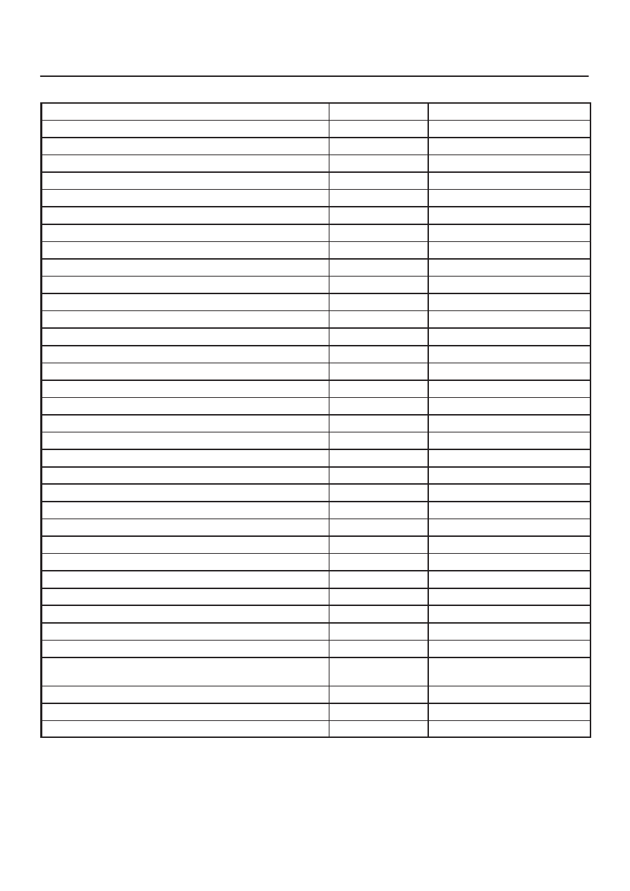
TRANSMISSION CONTROL SYSTEM (4L30–E)
7A1–19
Transmission Data
Item
Unit
Engine running at idle
Ignition Voltage
V
12.8
∼
14.1 V
Engine Speed
RPM
750
∼
900 RPM
Vehicle Speed
km/h, MPH
0 MPH
AT Output Speed (Automatic Transmission)
RPM
0 RPM
AT Input Speed Ratio (Automatic Transmission)
0.0
Throttle Position
%
0 %
AT Oil Temperature (Automatic Transmission)
°
C,
°
F
70
∼
80
°
C (158
∼
176
°
F)
AT Oil Temperature Lamp (Automatic Transmission)
Off, On
Off
AT Oil Life Monitor (Automatic Transmission)
%
100 %
AT Oil Life Lamp (Automatic Transmission)
Off, On
Not used
Commanded Gear
1
Current Gear
1
Mode Switch A
Inactive, Active
Active
Mode Switch B
Inactive, Active
Inactive
Mode Switch C
Inactive, Active
Inactive
Mode Switch G
Inactive, Active
Active
Selector Position
Park
1–2 Shift Solenoid A
Off, On
Off
2–3 Shift Solenoid B
Off, On
On
Solenoid Brake Band
Off, On
Off
TCC Slip Speed
RPM
750
∼
900 RPM
TCC Solenoid
Off, On
Off
TCC Duty Cycle
%
0 %
PCS Current (Pressure Control Solenoid)
A
approx. 1.0 A
PCS Duty Cycle (Pressure Control Solenoid)
%
approx. 45 %
Desired PCS Pressure (Pressure Control Solenoid)
kPa
43
∼
52 kPa
Shift Pressure
kPa
43
∼
52 kPa
Brake Switch
Off, On
On
Kickdown Switch
On, Off
Not used
Winter Switch
On, Off
Off
Winter Drive Lamp
Off, On
Off
Power Switch
Power Drive Nor-
mal
Normal
Power Drive Lamp
Off, On
Off
Emergency Mode
Off, On
Off
ABS Status
On, Off
Off