Content .. 2382 2383 2384 2385 ..
Opel Frontera UBS. Manual - part 2384
6A – 10 ENGINE MECHANICAL
8. Check the engine oil level and replenish to the
specified level if required.
9. Start the engine and check for oil leakage from the
main oil filter.
FUEL SYSTEM
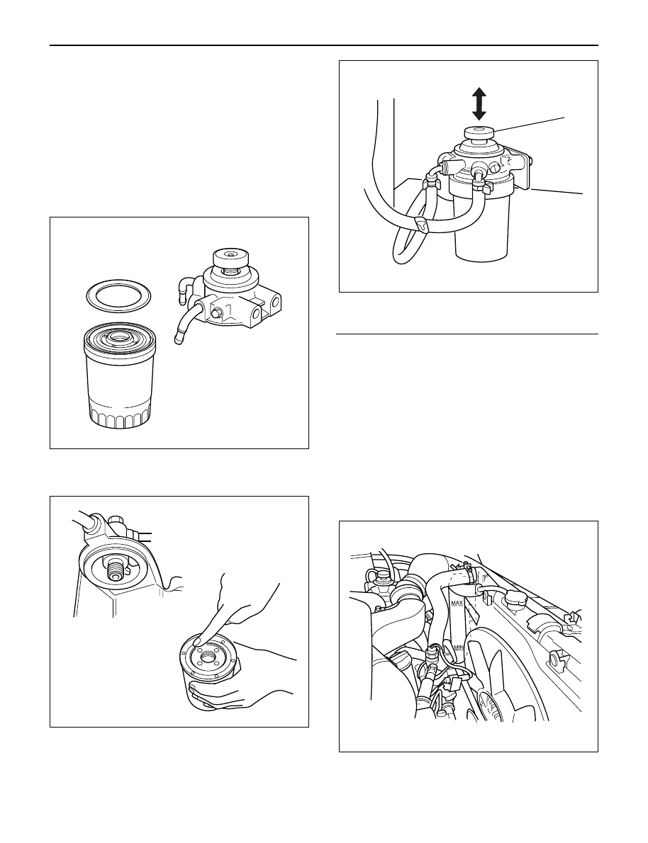
Fuel filter
Replacement Procedure
1. Loosen the used fuel filter by turning it
counterclockwise with the filter wrench.
Filter Wrench : 5-8840-0203-0
2. Clean the filter cover fitting faces.
This will allow the new fuel filter to seat properly.
3. Apply a light coat of engine oil to the O-ring.
4. Turn the fuel filter until the sealing face comes in
contact with the O-ring.
5. Turn the fuel filter with a filter wrench 2/3 of a turn
until sealed.
Filter Wrench: 5-8840-0203-0
Legend
(1) Priming pump
6. Operate the priming pump until the air is discharged
completely from fuel system.
NOTE: The use of an Isuzu genuine fuel filter is
strongly recommended.
COOLING SYSTEM
Coolant Level
Check the coolant level and replenish the radiator
reserve tank as necessary.
If the coolant level falls below the “‘MIN” line, carefully
check the cooling system for leakage. Then add
enough coolant to bring the level up to the “MAX” line.
NOTE: Do not overfill the reserve tank.
012RW112
012RW078
1
012RW111
012RW080