Content .. 2364 2365 2366 2367 ..
Opel Frontera UBS. Manual - part 2366
6E–500
6VE1 3.5 ENGINE DRIVEABILITY AND EMISSIONS
Accelerator Position Sensor
Replacement
CAUTION: Remove the Accelerator (A) pedal
assembly as a unit to have it serviced. Do not remove
the Accelerator Position (AP) sensor on the A pedal.
If the AP sensor is removed for emergency cause,
refer to following items as necessary.
Removal Procedure
1. Disconnect the negative battery cable.
2. Disconnect the electrical harness from the AP sensor.
060R200233
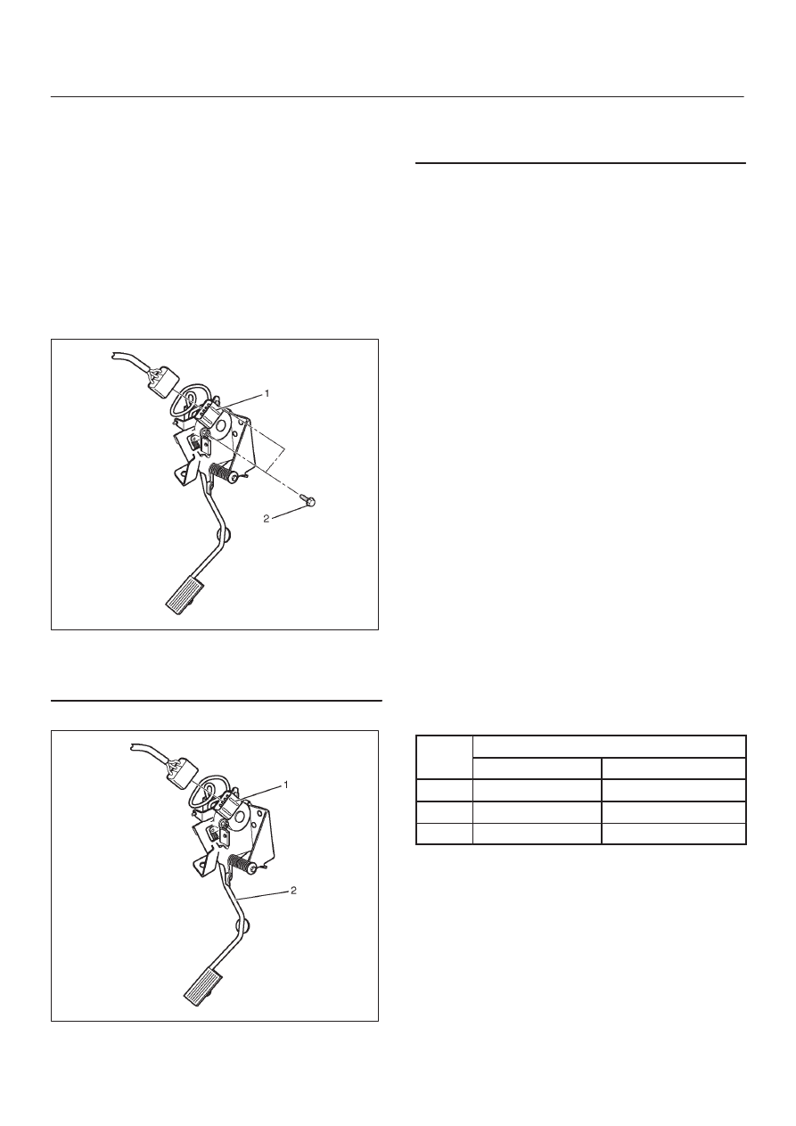
Legend
(1) AP Sensor
(2) A Pedal Assembly
3. Remove the AP sensor.
060R200235
Legend
(1) AP Sensor
(2) AP Screw
4. Remove all grease residues from the Accelerator
Position Sensor mounting
5. Clean all connector pins with contact cleaner. Use
LOCTITE
/ Permatex Electrical Contact Cleaner, or
equivalent.
NOTE: Do not use brake cleaner or carburetor spray.
Installation Procedure
1. Install the accelerator position (AP) sensor to bolts
with accelerator (A) pedal.
2. Connect the connector to AP sensor.
3. Install the negative battery cable.
Accelerator Position Sensor
Adjustment
AP sensor is controled three maltiple control system, and
adjust the idle position and WOT position are between A
and B for AP sensor 1, AP sensor 2, and AP sensor 3.
Refer to
“How to adjust for AP sensor”.
Removal Procedure
1. Disconnect the negative battery cable.
2. Disconnect the electrical harness from the AP sensor.
How To Adjust For AP Sensor
1. Connect the Tech 2 to DLC on vehicle.
2. Ignition “ON,” engine “OFF.”.
3. Display the APS date list. Check the following item for
AP position (%).
AP position (%)
Idle position A
WOT position B
APS1
11 – 15%
85 – 89%
APS2
85 – 89%
11 – 15%
APS3
85 – 89%
32 – 36%