Opel Frontera UBS. Manual - part 2365


  Index      Opel     Opel Frontera UBS - service repair manual 1998-2002 year


Search            


Content   ..  2363  2364  2365  2366   ..


Opel Frontera UBS. Manual - part 2365


6E–496

6VE1 3.5 ENGINE DRIVEABILITY AND EMISSIONS

EEPROM

General Description

The Electronically Erasable Programmable Read Only
Memory (EEPROM) is a permanent memory that is
physically soldered within the PCM.  The EEPROM
contains program and calibration information that the
PCM needs to control powertrain operation.

EEPROM Programming

1. Set-up – Ensure that the following conditions have

been met:

D

The battery is fully charged.

D

The ignition is “ON.”

D

The Vehicle Interface Module cable connection at
the DLC is secure.

2. Program the PCM using the latest software matching

the vehicle.  Refer to up-to-date Techline equipment
user’s instructions.

3. If the PCM fails to program, proceed as follows:

D

Ensure that all PCM connections are OK.

D

Check the Techline equipment for the latest
software version.

D

Attempt to program the PCM.  If the PCM still
cannot be programmed properly, replace the PCM.
The replacement PCM must be programmed.

Functional Check

1. Perform the On-Board Diagnostic System Check.
2. Start the engine and run for one minute.
3. Scan for DTCs using the Tech 2.

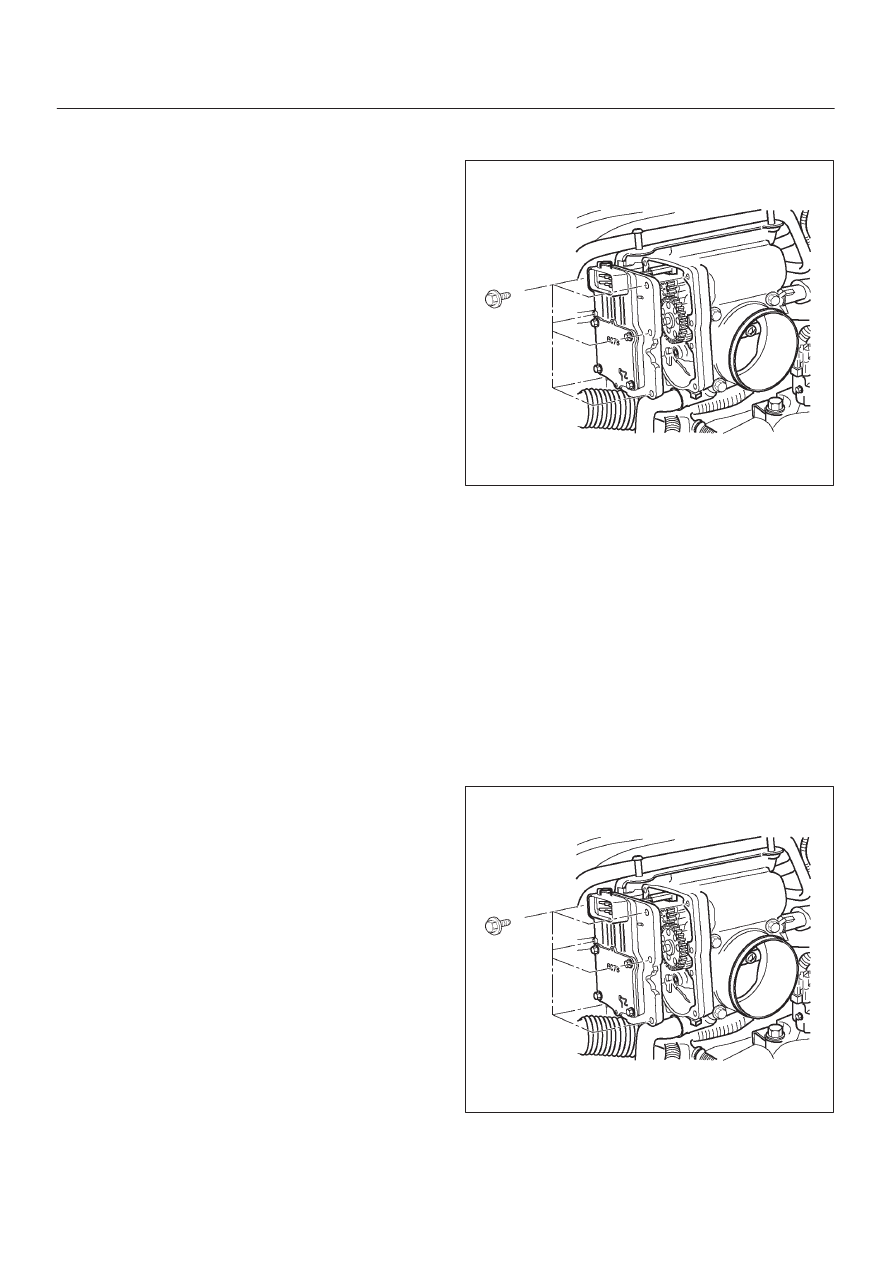
Throttle Position (TP) Sensor

Removal Procedure

1. Disconnect the negative battery cable.
2. Disconnect the TPS electrical connector.

3. Remove the bolts and the TP sensor from the throttle

body.

060R200185

NOTE: Do not clean the TP sensor by soaking it in
solvent.  The sensor will be damaged as a result.

Function Check

Use a Tech 2 to check the TP sensor output voltage at
closed throttle.

D

The voltage should be TP1 about 0.4V, TP2 about
4.6V and TP3 about 4.6V.

D

If the reading is abnormal value, check the throttle
shaft to see if it is binding.

Installation Procedure

1. Install the TP sensor on the throttle body with the

bolts.

060R200185

2. Connect the TP electrical connector.
3. Install the negative battery cable.

6E–497

6VE1 3.5L ENGINE DRIVEABILITY AND EMISSIONS

Vehicle Speed Sensor (VSS)

Removal Procedure

CAUTION: The VSS is located on the right side of
the transfer case just ahead of the rear propeller
shaft and very close to the exhaust pipes for 4WD
and on the extension cover for 2WD.  Be sure that the
exhaust pipes are cool enough to touch before trying
to remove the VSS.  If the pipes are hot, you could be
burned.

1. Disconnect the negative battery cable.
2. Disconnect the VSS electrical connector.

TS23748

3. Remove the bolt and the clamp securing the VSS in

place.

IMPORTANT:

Have a container ready to catch any fluid

that leaks out when the VSS is removed from the transfer
case for 4WD and on the extension cover for 2WD.

TS23780

4. Remove the VSS from the transfer case by wiggling it

slightly and pulling it straight out.

Inspection Procedure

1. Inspect the electrical connector for signs of corrosion

or warping.  Replace the VSS if the electrical
connector is corroded or warped.

2. Inspect the VSS driven gear for chips, breaks, or worn

condition.  Replace the VSS if the driven gear is
chipped, broken or worn.

3. Inspect the O-ring for wear, nicks, tears, or

looseness.  Replace the O-ring if necessary.

Installation Procedure

1. Install the VSS in the transfer case with the notch for

the connector facing the rear.

2. Secure the VSS in place with the clamp and the bolt.

Tighten

D

Tighten the bolt to 16 N·m (12 lb ft.).

TS23780

3. Connect the VSS electrical connector.

TS23748

4. Check the transfer case oil level.  Add fluid if

necessary.

5. Connect the negative battery cable.

6E–498

6VE1 3.5 ENGINE DRIVEABILITY AND EMISSIONS

Air Cleaner/Air Filter

Removal Procedure

1. Loosen the clamp between the air cleaner lid and the

mass air flow sensor.

060R200240

2. Release the four latches securing the lid to the air

cleaner housing.

3. Remove the air cleaner lid.
4. Remove the air filter element.
5. Remove the retaining bolts and the air cleaner

housing from the vehicle.

060R200220

Legend

(1) Air Cleaner Lid
(2) Air Filter Element
(3) Air Cleaner Housing

Installation Procedure

1. Install the air cleaner housing in the vehicle with the

retaining bolts.

2. Install the air filter element in the air cleaner housing.
3. Install the air cleaner lid on the MAF sensor and the air

cleaner housing.

060R200241

Legend

(1) Air Cleaner Lid
(2) Air Filter Element
(3) Air Cleaner Housing
(4) Mass Air Flow Sensor

4. Tighten the clamp and secure the four latches

between the lid and the air cleaner housing.

Common Chamber

Removal and Installation Procedure

Refer to Common Chamber in Engine Mechanical
section.

6E–499

6VE1 3.5L ENGINE DRIVEABILITY AND EMISSIONS

Accelerator Pedal Replacement

Removal Procedure

1. Disconnect the negative battery cable.
2. Disconnect the electrical harness from the

accelerator position sensor.

060R200233

Legend

(1) Accelerator Position Sensor
(2) Accelerator Pedal Assembly

3. Remove the two screws from the accelerator pedal

assembly.

060R200234

4. Remove the accelerator pedal assembly from the

bulkhead.

Installation Procedure

1. Install the accelerator pedal assembly on the

bulkhead.

2. Install the two screws to the accelerator pedal

assembly.

Tighten

D

Tighten the screws to 22 N·m (16 lb ft.).

060R200234

3. Connect the electrical harness to the accelerator

position sensor.

060R200233

Legend

(1) Accelerator Position Sensor
(2) Accelerator Pedal Assembly

4. Install the negative battery cable.


Content   ..  2363  2364  2365  2366   ..