Opel Frontera UBS. Manual - part 2183


  Index      Opel     Opel Frontera UBS - service repair manual 1998-2002 year


Search            


Content   ..  2181  2182  2183  2184   ..


Opel Frontera UBS. Manual - part 2183


6E–305

ENGINE DRIVEABILITY AND EMISSIONS

D

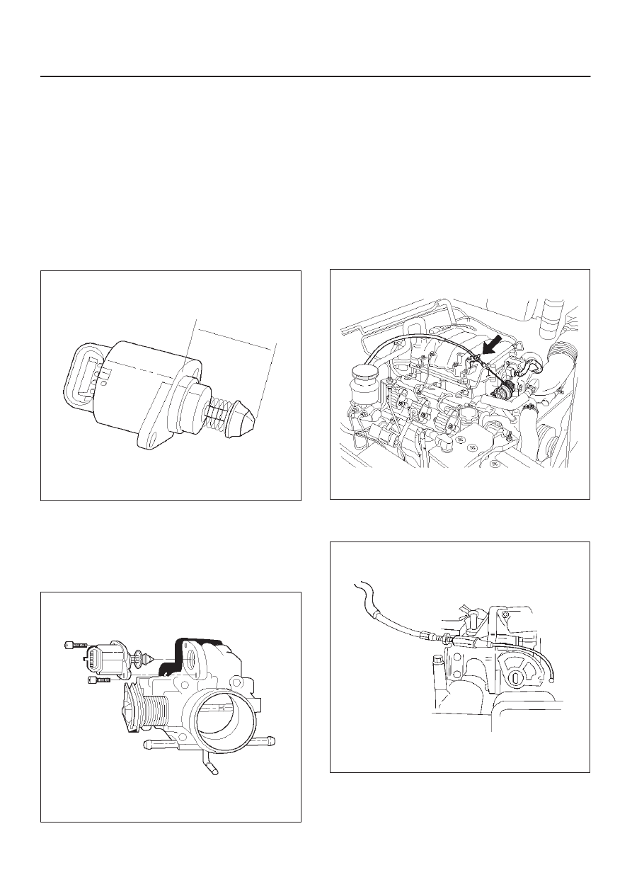
In order to install a new IAC valve, measure the
distance between the tip of the pintle and the
mounting flange.  If that measurement is 28 mm (1.1
in.) or less, the valve needs no adjustment.  If the
measurement is greater than 28 mm (1.1 in.), apply
finger pressure and retract the valve.  The force
required to retract the pintle on a new valve will not
damage the valve, shaft, or pintle.

NOTE: Do not push or pull on the IAC valve pintle on IAC
valves that have been in service.  The force required to
move the pintle may damage it.

IMPORTANT:

Use an identical replacement part in

order to replace a valve.  IAC valve pintle shape and
diameter are designed for the specific application.

TS23746

Installation Procedure

1. Install the IAC valve on the throttle body with the bolts.

Tighten

D

Tighten the bolts to 1 N·m (9 lb in.).

TS23745

2. Connect the IAC valve electrical connector.
3. Install the negative battery cable.

Common Chamber

Removal and Installation Procedure

Refer to Common Chamber in Engine Mechanical.

Accelerator Cable Assembly

Removal Procedure

1. Remove the engine cover.
2. Loosen the adjusting nut on the cable bracket

mounting on the common chamber.

101RW005

3. Remove the accelerator control cable (on the throttle

valve end).

101RW006

6E–306

ENGINE DRIVEABILITY AND EMISSIONS

4. Remove the accelerator control cable (on the

accelerator pedal end).

TS23982

5. Remove the grommet.
6. Remove the accelerator control cable.

TS23983

Inspection Procedure
Check the following items, and replace the control cable if
any abnormality is found:

D

The control cable should move smoothly.

D

The control cable should not be bent or kinked.

D

The control cable should be free of damage and
corrosion.

Installation Procedure

1. Install the accelerator control cable.

TS23983

2. Install the grommet.
3. Install the accelerator control cable (on the

accelerator pedal end).

TS23982

6E–307

ENGINE DRIVEABILITY AND EMISSIONS

4. Install the accelerator control cable (on the throttle

valve end).

101RW006

5. Install the adjusting nut.

101RW007

6. Adjust the accelerator cable at the throttle body.

Refer to 

Accelerator Cable Adjustment.

7. Install the engine cover.

Adjustment Procedure

1. Loosen the adjusting nut and lock nut.
2. Pull outer cable closing fully the throttle valve.
3. Tighten adjusting nut and lock nut temporarily.

035RW004

4. Loosen adjusting nut by three turns and tighten lock

nut. Then, manually operating the throttle valve,
make sure that the valve lever returns up to the
stopper screw.

IMPORTANT:

The valve lever must return up to the

stopper screw.  If the valve lever does not reach the
stopper screw, repeat the procedure again from step 1.

5. It does not reach the stopper screw, repeat from step

1.

TS23782

6E–308

ENGINE DRIVEABILITY AND EMISSIONS

Accelerator Pedal Replacement

Removal Procedure

1. Disconnect the cruise control cable from the

accelerator pedal assembly.

TS24053

2. Disconnect the accelerator pedal control cable from

the accelerator pedal assembly.

TS24054

3. Disconnect the wiring harness from the kick-down

switch.

TS24038

4. Remove the two screws from the accelerator pedal

assembly.

TS24055

5. Remove the accelerator pedal assembly from the

bulkhead.


Content   ..  2181  2182  2183  2184   ..