Content .. 2179 2180 2181 2182 ..
Opel Frontera UBS. Manual - part 2181
6E–297
ENGINE DRIVEABILITY AND EMISSIONS
Mass Air Flow (MAF) Sensor
Removal Procedure
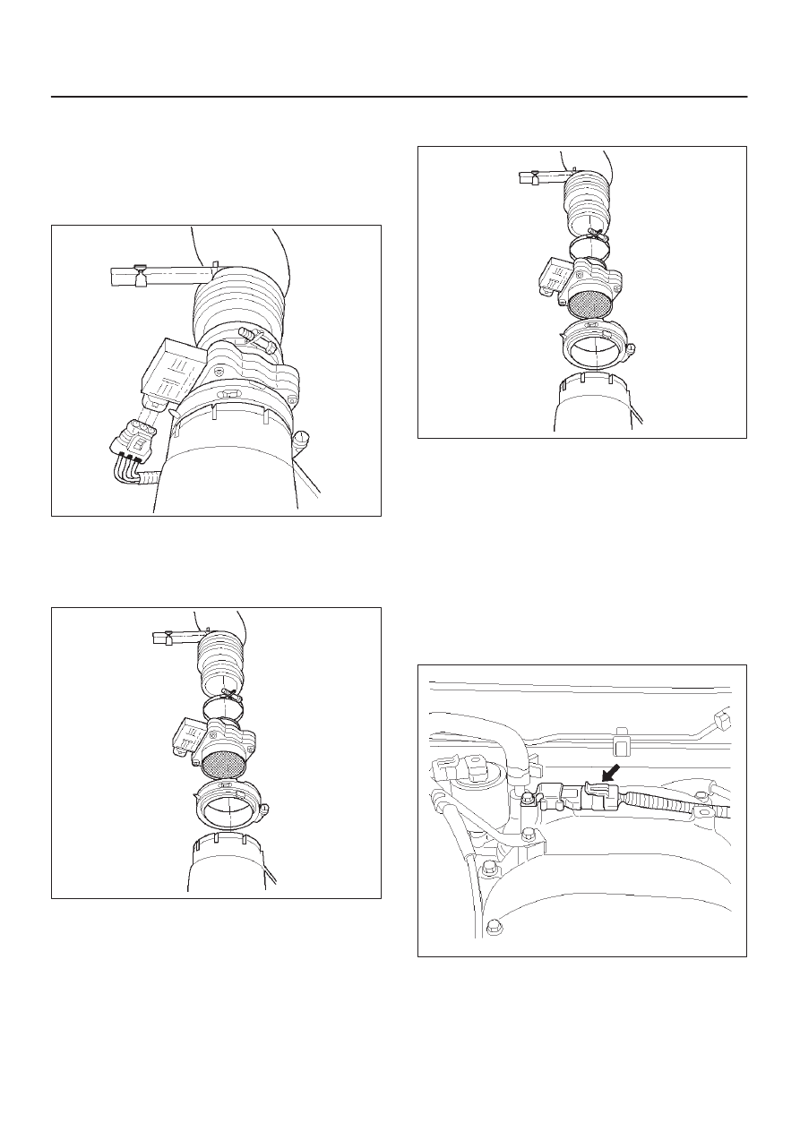
1. Disconnect the negative battery cable.
2. Disconnect the electrical connector from the MAF
sensor.
TS23740
3. Loosen the clamps which secure the intake air duct
and the air cleaner to the MAF sensor.
4. Remove the intake air duct from the MAF sensor.
5. Remove the MAF sensor from the air cleaner.
TS23781
Installation Procedure
1. Install the MAF sensor on the air cleaner with the
clamp.
2. Install the intake air duct and the clamp on the MAF
sensor.
TS23781
3. Tighten the clamps to secure the MAF sensor to the
intake air duct and the air cleaner.
4. Connect the MAF electrical connector.
5. Connect the negative battery cable.
Manifold Absolute Pressure
(MAP) Sensor
Removal Procedure
1. Disconnect the negative battery cable.
2. Disconnect the electrical connector from the MAP
sensor.
055RW005
3. Remove the bolt securing the MAP sensor to the
mounting bracket on the common chamber.