Opel Frontera UBS. Manual - part 2012


  Index      Opel     Opel Frontera UBS - service repair manual 1998-2002 year


Search            


Content   ..  2010  2011  2012  2013   ..


Opel Frontera UBS. Manual - part 2012


TRANSFER CASE (STANDARD TYPE)

4D1–17

2. Remove the rear output shaft assembly (1) from the

transfer rear cover (with oil seal).

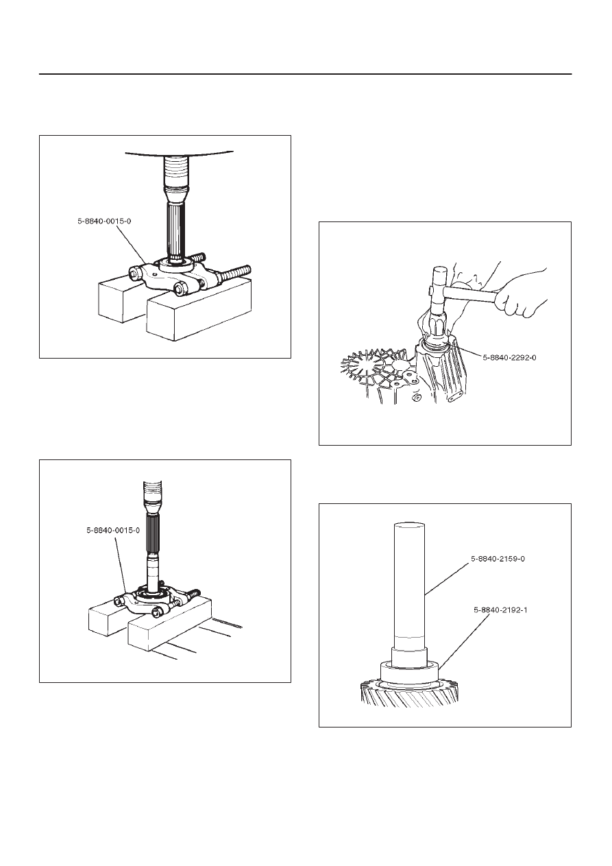
3. Remove ball bearing (8), using a bench press and the

bearing remover 5–8840–0015–0 (J–22912–01) .

226RW186

4. Remove the speedometer drive gear (7).
5. Remove the ball (6).
6. Remove the bearing snap ring (5), using a pair of snap

ring pliers.

7. Remove the ball bearing (4) from the rear output

shaft, using a bench press and the bearing remover
5–8840–0015–0 (J–22912–01).

226RW187

Inspection and Repair

Refer to “TRANSFER CASE ASSEMBLY” in this section
for inspection and repair.

Reassembly

1. Install transfer rear cover (with oil seal).

Oil seal replacement

D

Remove the oil seal from the transfer rear cover.

D

Apply engine oil to the oil seal outer surfaces.

D

Fill in recommended grease (BESCO L2) or
equivalent in the oil seal lip.

D

Use the oil seal installer 5–8840–2292–0 (J–39208)
to install the rear oil seal to the transfer rear cover.

220RW104

2. Set the snap ring (3), and install ball bearing (4) to the

rear output shaft (2), using the ball bearing installer
5–8840–2159–0 (J–37223) and the adapter
5–8840–2192–1 (J–37486–A).

262RW068

4D1–18 TRANSFER CASE (STANDARD TYPE)

3. Install the bearing snap ring (5).
4. Install the ball (6).
5. Install the speedometer drive gear (7).

226RS064

6. Install ball bearing (8), using the ball bearing installer

5–8840–2159–0 (J–37223).

226RW188

7. Install the rear output shaft assembly (1) to the

transfer rear cover.

8. Install the bearing snap ring (3).

NOTE: The snap ring must be fully inserted into the
transfer rear case snap ring groove.

TRANSFER CASE (STANDARD TYPE)

4D1–19

Transfer Rear Cover Assembly (Except 4WD Switch Model)

Transfer Rear Cover Assembly and Associated Parts

220RW116

Legend

(1) Speedometer Sensor, Speedometer Driven

Gear and Plate

(2) Front Companion Flange

(3) Rear Companion Flange
(4) Control Box Assembly
(5) Transfer Rear Cover Assembly
(6) Transfer Case Assembly

4D1–20 TRANSFER CASE (STANDARD TYPE)

Removal

1. Remove the speedometer sensor.
2. Remove the plate.
3. Remove the speedometer driven gear bushing and

driven gear.

NOTE: Apply a reference mark to the driven gear bushing
before removal.

4. Remove the front companion flange and the rear

companion flange, using the flange companion holder
5–8840–0133–0 (J–8614–11) to remove the end
nuts.

262RW067

NOTE: Use a universal puller to remove the rear
companion flange.

5. Disconnect the transfer breather hose from the

control box.

6. Remove the control box assembly.
7. Remove the transfer rear cover assembly from the

transfer case assembly.

Installation

1. Apply the recommended liquid gasket (LOCTITE

17430) or its equivalent to the transfer rear cover
fitting faces.

220RS017

2. Install the transfer rear cover assembly to the transfer

case assembly.

3. Perform the following steps before fitting the transfer

rear case:
1. Shift the high–low shift rod to the 4H side.

2. Turn the select rod counterclockwise so that the

select block projection may enter into the
2WD–4WD shift block.

3. The cut–away portion of the select rod head (9)

should align with that of the rear case hole’s
stopper (10).

230RW004

4. Tighten the transfer rear case bolts to the specified

torque.

Torque: 37 N·m (3.8kg·m/27 lb ft)


Content   ..  2010  2011  2012  2013   ..