Opel Frontera UBS. Manual - part 2011


  Index      Opel     Opel Frontera UBS - service repair manual 1998-2002 year


Search            


Content   ..  2009  2010  2011  2012   ..


Opel Frontera UBS. Manual - part 2011


TRANSFER CASE (STANDARD TYPE)

4D1–13

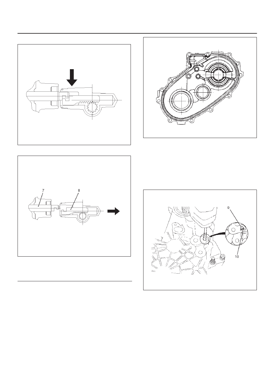
10. Offset the actuator assembly.

220RW028

11. Remove the actuator assembly.

220RW029

Legend

(7) Position: 4WD
(8) Mode: 2WD

12. Remove the transfer rear cover assembly from the

transfer case assembly.

Installation

1. Apply the recommended liquid gasket (LOCTITE

17430) or its equivalent to the transfer rear cover
fitting faces.

220RS017

2. Install the transfer rear cover assembly to the transfer

case assembly.

3. Perform the following steps before fitting the transfer

rear case:
1. Shift the high–low shift rod to the 4H side.

2. The cut–away portion of the select rod head (9)

should align with that of the rear case hole’s
stopper (10).

230RW004

4. Tighten the transfer rear case bolts to the specified

torque.

Torque: 37 N·m (3.8kg·m/27 lb ft)

5. Shift the 2WD–4WD shift rod (11) to the 4WD side.

4D1–14 TRANSFER CASE (STANDARD TYPE)

6. Join the rod grooves of 2WD–4WD actuator

assembly (12) and shift rod (11).

220RW030

Legend

(11) Shift Rod: 2WD–4WD (Position: 4WD)

(12) 2WD–4WD Actuator Assembly (Mode: 2WD)
(13) Rear Cover Assembly

7. Push the 2WD–4WD actuator assembly (12) with

2WD–4WD shift rod (11) till the shift rod (11) reaches
the 2WD position.

220RW031

Legend

(14) Position: 2WD
(15) Mode: 2WD

8. Tighten the 2WD–4WD actuator bolts to the specified

torque.

Torque: 19 N·m (1.9kg·m/14 lb ft)

9. Install the actuator heat protector.

10. Connect the actuator breather hose to the actuator.

11. Install the control box assembly.

Torque: 19 N·m (1.9kg·m/14 lb ft)

12. Connect the breather hoses to the control box.
13. Install the rear companion flange and front

companion flange, using the companion flange holder
5–8840–0133–0 (J–8614–11) to tighten the flange
nuts to the transfer case.

262RW067

14. Tighten the new transfer flange nuts to the specified

torque.

Torque
Rear companion flange: 167 N·m (17.0kg·m/123
lb ft)
Front companion flange: 137 N·m (14.0kg·m/101
lb ft)

15. Use the punch 5–8840–2293–0 (J–39209) to stake

the rear companion flange nut at two spots.

266RW027

TRANSFER CASE (STANDARD TYPE)

4D1–15

266RW002

16. Stake the front companion flange nut at one spot.

NOTE: Be sure to confirm that there is no crack at the
staked portion of the flange nut after staking.

17. Install the O–ring (8) to the speedometer driven gear

bushing (7).

18. Install the driven gear to the speedometer driven gear

bushing (7).

19. Install the speedometer driven gear assembly to the

transfer rear cover.

20. Install the plate (6) to the transfer rear case and

tighten to the specified torque.

Torque: 15 N·m (1.5kg·m/11 lb ft)

21. Install the speedometer sensor and tighten to the

specified torque.

Torque: 27 N·m (2.8kg·m/20 lb ft)

225RW014

4D1–16 TRANSFER CASE (STANDARD TYPE)

Disassembly

226RW154

Legend

(1) Rear Output Shaft Assembly
(2) Rear Output Shaft
(3) Bearing Snap Ring
(4) Ball Bearing

(5) Bearing Snap Ring
(6) Ball
(7) Speedometer Drive Gear
(8) Ball Bearing
(9) Transfer Rear Cover (with oil seal)

1. Remove the bearing snap ring (3), using a pair of snap

ring pliers.

226RS060


Content   ..  2009  2010  2011  2012   ..