Opel Frontera UBS. Manual - part 1526


  Index      Opel     Opel Frontera UBS - service repair manual 1998-2002 year


Search            


Content   ..  1524  1525  1526  1527   ..


Opel Frontera UBS. Manual - part 1526


7B–58 MANUAL TRANSMISSION

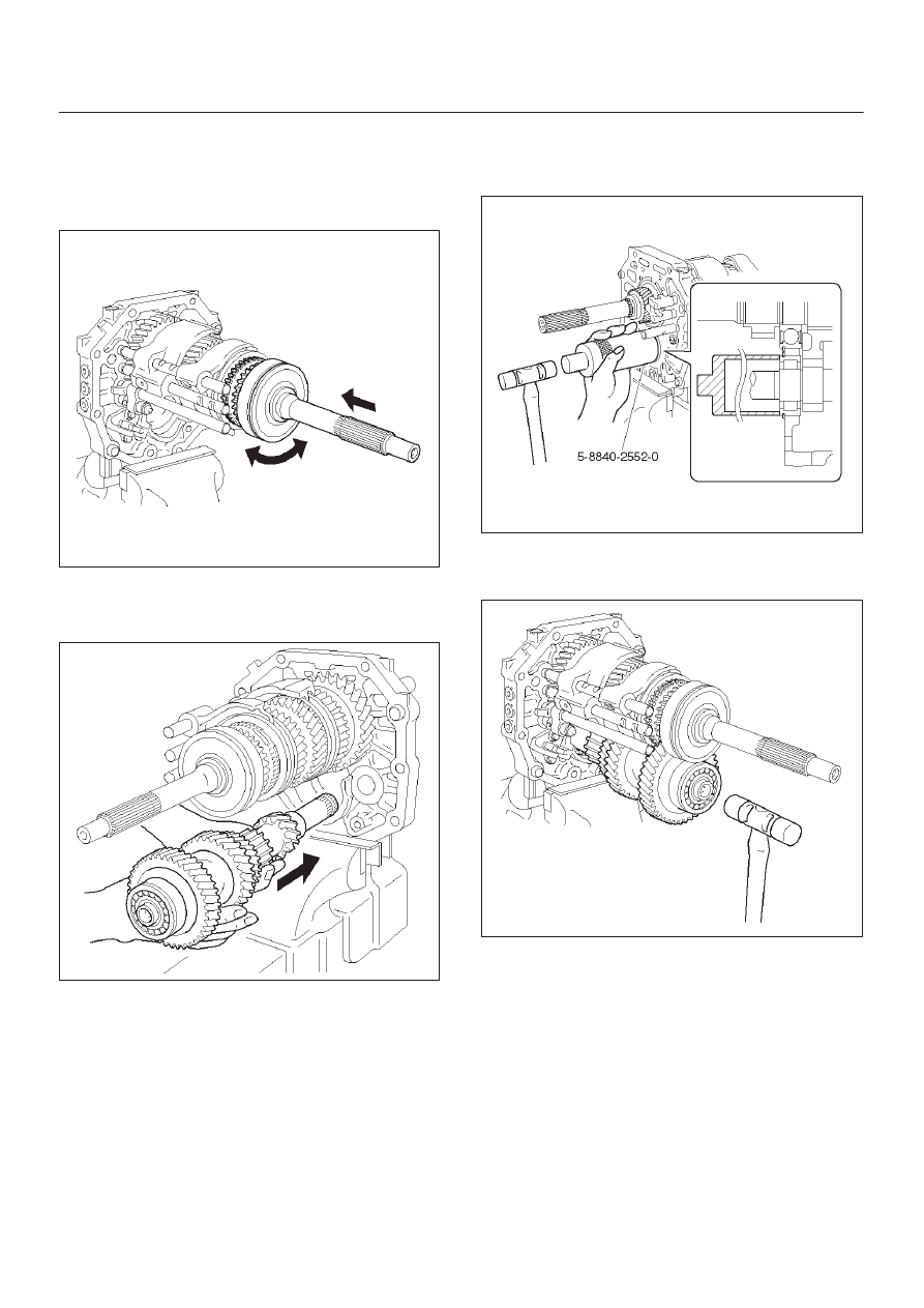
26. Install the top gear shaft.

1. Align the projection of the hub No.2 with the

synchronizer ring slots, and install the top gear
shaft assembly to the mainshaft.

2. Check that the gear rotates smoothly.

226RW006

27. Install the counter gear shaft.

1. Temporarily install the counter gear shaft to the

intermediate plate.

226RW028

2. Using installer 5–8840–2552–0 (J–42796) and a

hammer, drive in the center bearing as shown.

NOTE: Outer race snap ring groove toward rear.

226RW192

Reference: Drive in the counter rear bearing
by tapping on the front end of the counter
shaft.

226RW022

MANUAL TRANSMISSION

7B–59

28. Install the reverse idle gear.

1. Install the reverse idle gear and reverse idle gear

shaft.

NOTE:

D

Insert the reverse idle gear shaft with the slot toward
rear.

D

Install the reverse idle gear with the reverse shift arm
No.2.

226RW019

29. Install the bearing plate.

1. Align the bearing plate to groove of the reverse

idle gear shaft.

Torque: 13 N·m (1.3 kg·m/113 lb in)

226RW016

30. Install the 5th gear thrust washer.

1. Install the 5th gear thrust washer pin to the

counter gear shaft.

2. Install the 5th gear thrust washer to the counter

gear shaft.

NOTE: Thrust washer must be assembled with the
chamfered face of the washer toward the front.

226RW185

31. Install the counter 5th gear.

1. Install the 3 inserts and 3 compression springs to

the reverse block ring.
Reference: Push the 3 inserts with the 3 com-
pression springs to the reverse synchronizer
ring.

226RW120

7B–60 MANUAL TRANSMISSION

2. Install the synchronizer outer ring, synchronizer

cone ring, and synchronizer pull ring to the
reverse block ring.

226RW121

3. Turn to 30 degree the reverse synchronizer pull

ring.

226RW080

4. Install the hub sleeve No.3 and reverse block ring

set to the counter 5th gear.

NOTE: Check the hub sleeve No.3 direction, as shown.

Reference: While pushing the 3 inserts,
install the synchronizer ring assembly to the
hub sleeve No.3.

226RW184

5. Slide the hub sleeve No.3.

226RW123

MANUAL TRANSMISSION

7B–61

6. Install the counter 5th gear bearing, counter 5th

gear and reverse block ring set to the counter
gear shaft, through the 5th reverse shift arm to the
5th reverse shift rod.

220RW101

7. Using installer 5–8840–2552–0 (J–42796) and a

press, install counter 5th gear spline piece.

NOTE:

D

Align the projection of the cone ring to the holes of the
5th gear spline piece.

D

Check that the gear rotates smoothly.

226RW193

8. Using thickness gauge, measure the counter 5th

gear thrust clearance.

Standard: 0.10 – 0.35mm (0.004 – 0.014 in)

220RW100

9. Select a snap ring that will allow minimum axial

play.

Mark

Thickness

A

2.80 – 2.85 (0.110 – 0.112 in)

B

2.85 – 2.90 (0.112 – 0.114 in)

C

2.90 – 2.95 (0.114 – 0.116 in)

D

2.95 – 3.00 (0.116 – 0.118 in)

E

3.00 – 3.05 (0.118 – 0.120 in)

F

3.05 – 3.10 (0.120 – 0.122 in)

G

3.10 – 3.15 (0.122 – 0.124 in)

226RW027


Content   ..  1524  1525  1526  1527   ..