Content .. 1319 1320 1321 1322 ..
Opel Frontera UBS. Manual - part 1321
6A – 34 ENGINE MECHANICAL
EXHAUST MANIFOLD
REMOVAL
1. Remove the hose from both turbocharger outlet and
intake manifold inlet side, then remove intercooler
assembly.
2. Loosen belt tensioner, remove A/C compressor
assembly.
3. Remove heat protector from turbocharger.
4. Remove water hoses and oil pipes from
turbocharger.
5. Remove turbocharger assembly from exhaust
manifold.
6. Remove exhaust manifold fixing nuts, then remove
exhaust manifold.
INSTALLATION
1. Install gasket on the exhaust manifold and tighten
to the specified torque.
Torque : 30 N·m (3.1 kg·m/22 lb ft)
2. Install turbocharger on the exhaust manifold.
Torque : 27 N·m (2.8 kg·m/20.2 lb ft)
3. Install water hoses and oil pipes.
4. Install heat protector to turbocharger.
Torque : 9 N·m (0.9 kg·m/6.5 lb ft)
5. Install A/C compressor assembly and readjust belt
tensioner.
6. Install the intercooler assembly in the normal
position.
Connect both hoses to turbocharger and intake
manifold.
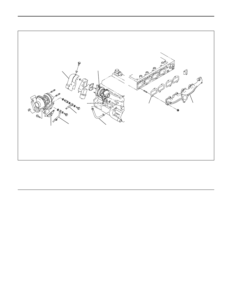
9
8
7
5
6
3
2
1
4
025RW023
Legend
(1)
Exhaust Manifold
(2)
Gasket
(3)
Turbocharger Assembly
(4)
Water Hose
(5)
Water Hose
(6)
Heat Protector
(7)
Oil Pipe
(8)
Oil Pipe
(9)
Gasket