Opel Frontera UBS. Manual - part 1322


  Index      Opel     Opel Frontera UBS - service repair manual 1998-2002 year


Search            


Content   ..  1320  1321  1322  1323   ..


Opel Frontera UBS. Manual - part 1322


6A – 38 ENGINE MECHANICAL

1. Cylinder head bolts for damaged threads or

stretching and damaged heads caused by improper
use of tools.

CAUTION: Suspected bolts must be replaced.

2. Cylinder head for cracks, especially between valve

seats and in the exhaust ports.

3. Cylinder head deck for corrosion, sand particles in

head and porosity.

CAUTION: Do not attempt to weld the cylinder
head. Replace it.

4. Cylinder head lower surface for flatness.

Use a straight edge and a feeler gauge to measure
the cylinder head lower surface warpage.
If the measured values exceed the specified limit,
the cylinder head must be replaced.
Cylinder Head Lower Face Warpage:
Standard: 0.075 mm (0.0029 in) or less
Limit: 0.50 mm (0.0197 in)

Cylinder Head Height:
Standard: 95 mm (3.740 in)

5. Water jacket sealing plugs seating surfaces.
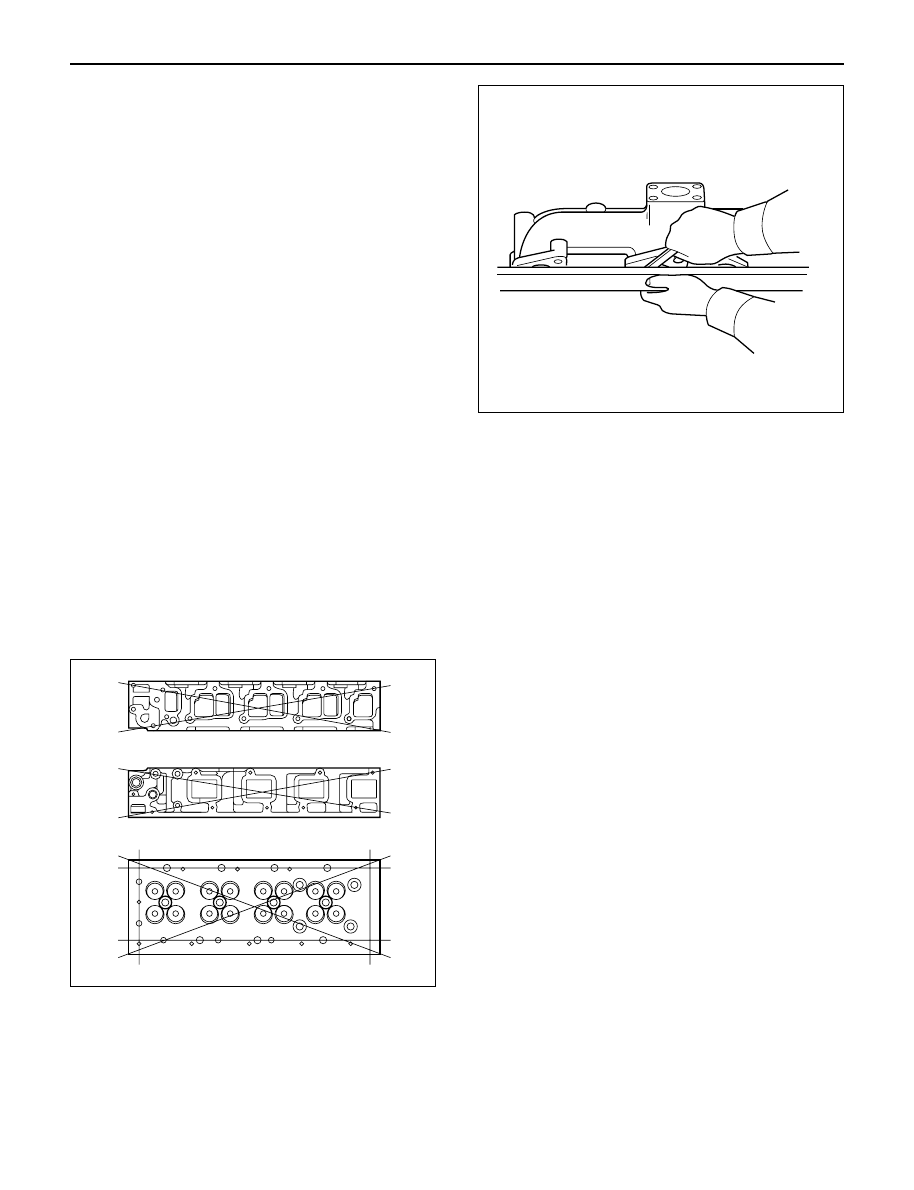
6. Use a straight edge and a feeler gauge to measure

the manifold cylinder head fitting face warpage.
If the measured values exceed the specified limit,
the manifold must be replaced.
Exhaust Manifold Warpage:
Standard: 0.05 mm (0.0020 in) or less
Limit: 0.20 mm (0.0079 in)

CAUTION: Do not attempt to weld the cylinder
head. Replace it.

REASSEMBLY

1. Cylinder Head

Refer to “Cylinder head”.

2. Glow Plug and Glow Plug Connector

Tighten glow plugs.

Torque: 15 N·m (1.5 kg·m/11 lb ft)

011RW006

012RW053

ENGINE MECHANICAL 6A – 39

CYLINDER HEAD GASKET

12

13

14

15

1

2

3

7

4

5

6

10

11

9

8

011RW047-1

Legend

(1)

Cylinder Head Noise Insulator Cover

(2)

Insulator

(3)

Bolt and Gasket

(4)

Oil Seal

(5)

Gasket

(6)

Cylinder Head Cover

(7)

Bolt and Gasket

(8)

Injector Clamp

(9)

Oil Rail

(10)

Injector Assembly

(11)

Camshaft Carrier

(12)

Cylinder Head Bolt

(13)

Cylinder Head Assembly

(14)

Cylinder Head Gasket

(15)

Cylinder Block

6A – 40 ENGINE MECHANICAL

REMOVAL

1. Disconnect battery ground cable.
2. Drain engine coolant.
3. Remove air cleaner and air duct.
4. Remove intercooler assembly.

Refer to “Intercooler” in this manual.

5. Remove oil level gauge guide assembly.
6. Remove PCV hose.
7. Remove EGR vacuum hose.
8. Disconnect harness connector around the cylinder

head.

9. Remove A/C compressor assembly.

10. Remove A/C compressor bracket.
11. Remove generator assembly and take out fan belt.
12. Remove heat protector and remove valve

assembly.

13. Remove water hose and oil pipe from turbocharger.
14. Remove turbocharger assembly.
15. Remove water hose between thermostat and

radiator.

16. Remove cylinder head noise insulator cover.

NOTE: Do not make damage to the harness.

17. Remove high pressure pipe.
18. Remove timing belt cover.
19. Remove CMP sensor bracket.
20. Remove timing belt tensioner and remove timing

belt.

21. Remove camshaft pulley.
22. Remove front plate.
23. Remove water pipe between cylinder head and

water pump.

24. Remove fuel pipe between fuel pump and intake

manifold.

25. Remove fuel return pipe.
26. Remove intake manifold assembly.
27. Disconnect glow plug wiring and remove glow plug.
28. Remove cylinder head cover.
29. Drain oil from oil rail.
30. Disconnect injector harness connector.
31. Disconnect harness connector from oil pressure

sensor and oil temperature sensor on the oil rail.

32. Disconnect injector harness assembly.
33. Remove injector clamp.
34. Remove injector spacer.
35. Remove injector assembly.
36. Remove oil rail assembly.
37. Remove camshaft carrier.
38. Remove cylinder head assembly.
39. Remove cylinder gasket.

INSTALLATION

1. Install cylinder head gasket with top mark up.

NOTE: Determine cylinder head gasket grade by
measuring projection of piston head.

2. Selection cylinder head gasket.

1) Measure the piston head projection by injector

gauge.

2) Measure the projection of piston head at the

nearest possible point to the cylinder bore.

3) Obtain the largest measurement from among all

cylinders.

4) Determine cylinder head gasket grade by

maximum value of measuring projection of
piston head.

Legend

(1) Top Mark
(2) Grade Mark

012RW073

2

1

011RW043

ENGINE MECHANICAL 6A – 41

Cylinder head gasket and piston projection 

mm

CAUTION:

The projection of each piston should be 0.333
mm or more and less than 0.483 mm.

Maximum difference in projection between
pistons should be less than 0.1 mm.

If the piston projection is without standard,
reassemble the engine all over again.

3. Install cylinder head assembly, tighten bolts by

angular tightening method.

Torque:

1st step;

49 N·m (4.9 kg·m/35.4 lb ft)

2nd step; 60°
3rd step; 60°

4. Install camshaft carrier assembly.

Refer to “Camshaft” in this manual.

5. Install oil rail and injector assembly.

Refer to “Oil rail and injector” in this manual.

6. Install injector harness to connect harness

connector.

Note: Apply liquid gasket (TB 1207B or equivalent) to
the rubber seal of the camshaft end, injector harness
gasket area and No. 1 camshaft bracket. Refer to the
Cylinder head cover.

7. Install cylinder head cover.

Torque: 9 N·m (0.9 kg·m/6.5 lb ft)

8. Install glow plug to tighten specified torque.

Torque: 15 N·m (1.5 kg·m/11 lb ft) and connect
glow plug harness.

9. Install intake manifold.

Torque: 20 N·m (2.0 kg·m/14.5 lb ft)
10. Install fuel return pipe.
11. Install fuel pipe in between fuel pump and intake

manifold.

12. Install water pipe in between cylinder head and

water pump.
Tighten flange bolt to the specified torque.

Torque: 20 N·m (2.0 kg·m/14.5 lb ft)
13. Install front plate.

Torque: 20 N·m (2.0 kg·m/14.5 lb ft)
14. Install camshaft pulley, tighten with angular

tightening method.

1st step 40 N·m (4.0 kg·m/29 lb ft)
2nd step 60°

NOTE: Apply engine oil to camshaft pulley bolt.

15. Align timing mark oil pump pulley and camshaft

pulley to front plate then put the timing belt and
tighten tensioner bolt.

Torque: 20 N·m (2.0 kg·m/14.5 lb ft) for M8

50 N·m (5.1 kg·m/37 lb ft)

16. Install CMP sensor bracket.
17. Install timing belt cover.

Torque: 9 N·m (0.9 kg·m/6.5 lb ft)
18. Fill with about 300 cc of engine oil from the high

pressure oil pipe installing port of oil rail using an oil
filler.
If assembled without filling the oil rail with oil, the
time for engine start will be longer.

19. Immediately install high pressure oil pipe to tighten

with specified torque.

Torque: 80 N·m (8 kg·m/57.9 lb ft)
20. Install cylinder head noise insulator cover.

Torque: 9 N·m (0.9 kg·m/6.5 lb ft)

Grade A

Grade B

Grade C

011RW042

Grade

Piston projection

Gasket

thickness

A

more 0.333 to less 0.383

1.35

B

more 0.383 to less 0.433

1.40

C

more 0.433 to less 0.483

1.45


Content   ..  1320  1321  1322  1323   ..