Opel Frontera UBS. Manual - part 1319


  Index      Opel     Opel Frontera UBS - service repair manual 1998-2002 year


Search            


Content   ..  1317  1318  1319  1320   ..


Opel Frontera UBS. Manual - part 1319


6A – 26 ENGINE MECHANICAL
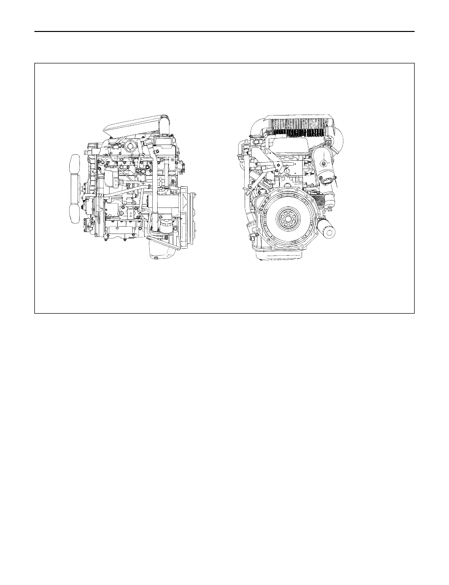
ENGINE ASSEMBLY

F06RW048

REMOVAL

1. Remove battery. 
2. Drain engine coolant
3. Disconnect window washer hose and remove

engine hood.

4. Radiator Hose

1) Disconnect upper and lower hoses from engine

side.

5. Fan Shroud

1) Disengage clips and remove upper and lower

fan shrouds.

6. Cooling Fan Assembly

1) Remove cooling fan assembly fixing nuts,

cooling fan assembly.

7. Radiator Assembly

1) Remove bracket and radiator assembly.

8. Air Cleaner Cover & Air Duct
9. Intercooler Assembly

1) Refer to “Intercooler” in this manual.

10. Engine Ground Cable

1) Disconnect ground cable from A/C compressor

bracket.

11. AC Generator Harness

1) Disconnect B terminal and harness connector

from AC generator.

12. A/C Compressor Assembly

1) Disconnect magnetic clutch harness connector.
2) Remove A/C compressor fixing bolt (rear under

side of compressor).

3) Remove fixing bolts (upper and front lower side

of compressor) and set A/C compressor
assembly with pipe lines on battery carrier.

13 Vacuum Hose

1) Disconnect vacuum hose from vacuum pump.

14. Starter Harness

1) Disconnect B terminal and put cable harness

close to chassis side.

2) Disconnect S terminal connector.

15. Engine Harness

1) Disconnect engine harness close to engine side.

16. Fuel Pipe

1) Remove fuel pipe from fuel pump and take care

not to spill fuel and let dust enter.

17. Engine Ground Cable

1) Disconnect ground cable from left rear side of

timing gear case.

18. Vacuum Hose: Vacuum Tank

Disconnect vacuum hose from vacuum pump side.

19. Glow Plug Harness
20. Transmission Assembly

1) Set transmission support tool under the

transmission.

ENGINE MECHANICAL 6A – 27

2) Remove transmission rear mount.
3) Remove transmission fixing bolt from rear of

engine assembly except two bolts.

4) Carefully hang up engine assembly with a hoist.
5) Remove remaining two transmission fixing bolts.
6) Remove transmission assembly.
7) Remove heater hose.
8) Disconnect wire harness connector for shift on

the fly.

9) Remove vacuum hose.

21. Prepare Engine Stand
22. Engine Assembly

1) Remove engine mount fixing bolts.
2) Carefully hang up the engine assembly.
3) Take out the engine assembly making sure not

to damage the brake oil pipe and other pipe etc.

INSTALLATION

1. Engine assembly

1) Install engine in mounting position by using

hoist.

2. Transmission Assembly

1) Refer to transmission installation steps in

section 7.

3. Engine Mounting

1) After all fixing bolts (left: two bolts, rights: two

bolts) were inserted in every hole, tighten fixing
bolts to the specified torque.

Torque: 40 N·m (4 kg·m/29 lb·ft)

4. Glow Plug Harness
5. Vacuum Hose

1) Connect Vacuum Hose to Vacuum Pump

6. Engine Ground Cable
7. Fuel Pipe

1) Install fuel pipe to fuel pump.

8. Engine Harness
9. Starter Harness

10. A/C Compressor Assembly

1) Tighten temporarily the fixing bolts (upper and

front lower sides of compressor.)

2) Tighten fixing bolt (rear under side of

compressor) to the specified torque.

3) Tighten fixing bolts (front upper and lower sides

of compressor) to the specified torque.

Torque: 40 N·m (4 kg·m/29 lb·ft)

Legend

(1) Tensioner
(2) Bolt
(3) Bracket
(4) A/C compressor
(5) Bolt

11. A.C Generator Harness
12. Engine Ground Cable

1) Tighten ground cable to A/C compressor

bracket.

13. Air Cleaner cover & Duct
14. Intercooler Assembly

1) Refer to “Intercooler” in this manual.

15. Radiator Assembly

1) Install rubber cushion in under left and right part

of radiator and position radiator.

2) Fix radiator with bracket.

16. Cooling Fan Assembly

1) Install cooling fan assembly and tighten fixing

bolts to the specified torque.

Torque: 8 N·m (0.8 kg·m/5.8 lb ft)

17. Fan Shroud
18. Radiator Hose

1) Connect upper and lower hose to engine side.
2) Pour coolant into radiator.

19. Install battery.
20. Connect window washer hose and install engine

hood.

1

2

3

4

5

F06RW054

6A – 28 ENGINE MECHANICAL

ENGINE MOUNT (RH)

REMOVAL

1. Disconnect battery ground cable
2. Hang the engine assembly.
3. Rubber engine mount.

1) Remove bolts from chassis frame bracket.
2) Remove nuts from rubber engine mount and

engine mounting bracket.

4. Remove bolt which is fixed between engine and

mounting bracket then remove the engine mounting
bracket.

INSTALLATION

Tighten the fixing bolts to the specified torque.

1. Engine mounting bracket to cylinder block.

Torque : 40 N·m (4 kg·m/29 lb ft) (for M10)

127 N·m (13 kg·m/94 lb ft) (for M14)

2. Rubber engine mount to chassis frame and engine

mounting bracket.

Torque :40 N·m (4 kg·m/29 lb ft)

4

3

1

2

022RW018

Legend

(1)

Rubber Engine Mount (LH)

(2)

Engine Mounting Bracket (LH)

(3)

Rubber Engine Mount (RH)

(4)

Engine Mounting Bracket (RH)

ENGINE MECHANICAL 6A – 29

ENGINE MOUNT (LH)

REMOVAL

1. Disconnect battery ground cable
2. Hang the engine assembly.
3. Rubber engine mount.

1) Remove bolts from chassis frame bracket.
2) Remove nuts from rubber engine mount and

engine mounting bracket.

4. Remove bolt which is fixed between engine and

mounting bracket then remove the engine mounting
bracket.

INSTALLATION

Tighten the fixing bolts to the specified torque.

1. Engine mounting bracket to cylinder block.

Torque : 40 N·m (4 kg·m/29 lb ft) (for M10)

127 N·m (13 kg·m/94 lb ft) (for M14)

2. Rubber engine mount to chassis frame and engine

mounting bracket.

Torque :40 N·m (4 kg·m/29 lb ft)

4

3

1

2

022RW018

Legend

(1)

Rubber Engine Mount (LH)

(2)

Engine Mounting Bracket (LH)

(3)

Rubber Engine Mount (RH)

(4)

Engine Mounting Bracket (RH)


Content   ..  1317  1318  1319  1320   ..